background image

30-4

PC09-1

DISASSEMBLY AND ASSEMBLY

PRECAUTIONS WHEN CARRYING OUT OPERATION

PRECAUTIONS WHEN CARRYING OUT OPERATION

[When carrying out removal or installation (disassembly or assembly) of units, be sure to follow the general pre-
cautions given below when carrying out the operation.]
1.

Precautions when carrying out removal work

 •

If the coolant contains antifreeze, dispose of it correctly.

 •

After disconnecting hoses or tubes, cover them or fit blind plugs to prevent dirt or dust from entering.

 •

When draining oil, prepare a container of adequate size to catch the oil.

 •

Confirm the match marks showing the installation position, and make match marks in the necessary places
before removal to prevent any mistake when assembling.

 •

To prevent any excessive force from being applied to the wiring, always hold the connectors when discon-
necting the connectors. Do not pull the wires.

 •

Fit wires and hoses with tags to show their installation position to prevent any mistake when installing.

 •

Check the number and thickness of the shims, and keep in a safe place.

 •

When raising components, be sure to use lifting equipment of ample strength.

 •

When using forcing screws to remove any components, tighten the forcing screws uniformly in turn.

 •

Before removing any unit, clean the surrounding area and fit a cover to prevent any dust or dirt from enter-
ing after removal.

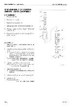
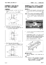
Precautions when handling piping during disassembly
Fit the following blind plugs into the piping after disconnecting it during disassembly operations.

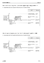
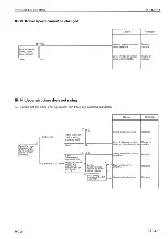
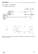
1)  Face seal type hoses and tubes

2)  Split flange type hoses and tubes
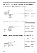
3)

If the part is not under hydraulic pressure, the following corks can be used.

Nominal 

number

Plug (nut end)

Nut (elbow end)

02

07376-70210

02789-00210 

03

07376-70315

02789-00315

04

07376-70422

02789-00422

05

07376-70522

02789-00522

06

07376-70628

02789-00628

Nominal 

number

Flange (hose end)

Sleeve head (tube end)

Split flange

04

07379-00400

07378-10400

07371-30400

05

07379-00500

07378-10500

07371-30500

Nominal 

number

Part Number

Dimensions

D

d

L

06

07049-00608

6

5

8

08

07049-00811

8

6.5

11

10

07049-01012

10

8.5

12

12

07049-01215

12

10

15

14

07049-01418

14

11.5

18

16

07049-01620

16

13.5

20

18

07049-01822

18

15

22

20

07049-02025

20

17

25

22

07049-02228

22

18.5

28

24

07049-02430

24

20

30

27

07049-02734

27

22.5

34

Содержание PC09-1

Страница 1: ...vailable in your area Please consult your local Komatsu distributor for those items you may require Materials and specifications are subject to change without notice PC09 1 mount the 2D68E N3C engine...

Страница 2: ......

Страница 3: ...10 32 10 34 10 35 10 36 10 37 10 38 10 39 10 40 10 41 20 1 20 2 20 3 20 4 20 5 20 6 20 7 20 8 Mark Page Revision number 20 9 20 10 20 101 1 20 101 1 1 20 102 20 103 20 104 20 105 20 106 20 107 20 108...

Страница 4: ...ron hand shield cap and other clothes suited for welding work 4 When carrying out any operation with two or more workers always agree on the operating procedure before starting Always inform your fell...

Страница 5: ...ring may cause electrical fires 17 When removing piping stop the fuel or oil from spilling out If any fuel or oil drips onto the floor wipe it up immediately Fuel or oil on the floor can cause you to...

Страница 6: ...tion may contain hydraulic circuit diagrams electric circuit diagrams and mainte nance standards TESTING AND ADJUSTING This section explains checks to be made before and after performing repairs as we...

Страница 7: ...ach item 3 Additional pages Additional pages are indicated by a hyphen and number after the page number File as in the example Example 10 4 10 4 1 10 4 2 10 5 REVISED EDITION MARK When a manual is rev...

Страница 8: ...vy load with one rope alone but sling with two or more ropes symmetrically wound onto the load Slinging with one rope may cause turning of the load during hoisting untwisting of the rope or slipping o...

Страница 9: ...ssure from hydraulic tank 2 Hold adapter 1 and push hose joint 2 into mating adapter 3 See Fig 1 The adapter can be pushed in about 3 5 mm Do not hold rubber cap portion 4 3 After hose joint 2 is push...

Страница 10: ...ght until sliding pre vention ring 1 contacts contact surface a of the hexagonal portion at the male end 2 Hold in the condition in Step 1 and push until cover 3 contacts contact surface a of the hexa...

Страница 11: ...or sealant for metal glass and plastic LT 4 790 129 9040 250 g Polyethylene container Used as sealant for machined holes Holtz MH 705 790 126 9120 75 g Tube Used as heat resisting sealant for repairi...

Страница 12: ...Can Used as lubricant for sliding por tion to prevent from squeaking LM P 09940 00040 200 g Tube Used to prevent seizure or scuf fling of the thread when press fit ting or shrink fitting Used as lubr...

Страница 13: ...113 010 177 019 1 35 00 15 3 2 00 3 6 7 00 7 11 5 01 18 02 16 18 20 22 24 24 27 30 32 36 279 030 382 039 549 059 745 083 927 0103 28 5 03 39 04 56 06 76 08 5 94 5 010 5 27 30 33 36 39 41 46 50 55 60...

Страница 14: ...kgm 10 12 16 14 17 22 65 7 06 8 112 09 8 279 029 6 7 00 7 11 5 01 28 5 03 Norminal No Thread diameter Width across flat Tightening torque mm mm Nm kgm 02 03 04 05 06 10 12 14 14 20 24 33 42 Varies de...

Страница 15: ...ter Tightening torque mm Nm kgm 6 8 10 12 14 8 02 10 02 12 02 24 04 36 05 0 81 00 20 1 02 00 20 1 22 00 20 2 45 00 41 3 67 00 51 Thread diameter Tightening torque inch Nm kgm 1 16 1 8 1 4 3 8 1 2 3 4...

Страница 16: ...ing and signal 15 84 0 45 13 36 7 0 59 Starting Glow plug 40 85 0 80 42 73 11 4 135 Starting 60 127 0 80 63 84 13 6 178 Starting 100 217 0 80 109 1 17 6 230 Starting Priori ty Circuits Classi fication...

Страница 17: ...by 10 move the decimal point one place to the left to convert it to 55 mm 2 Carry out the same procedure as above to convert 55 mm to 2 165 inches 3 The original value 550 mm was divided by 10 so mul...

Страница 18: ...3 819 0 315 0 709 1 102 1 496 1 890 2 283 2 677 3 071 3 465 3 858 0 354 0 748 1 142 1 536 1 929 2 323 2 717 3 110 3 504 3 898 0 1 2 3 4 5 6 7 8 9 0 10 20 30 40 50 60 70 80 90 0 22 05 44 09 66 14 88 1...

Страница 19: ...700 20 341 22 983 25 625 2 113 4 755 7 397 10 039 12 680 15 322 17 964 20 605 23 247 25 889 2 378 5 019 7 661 10 303 12 944 15 586 18 228 20 870 23 511 26 153 0 1 2 3 4 5 6 7 8 9 0 10 20 30 40 50 60 7...

Страница 20: ...62 0 1034 3 1106 6 1179 0 1251 3 1323 6 1396 0 28 9 101 3 173 6 245 9 318 3 390 6 462 9 535 2 607 6 679 9 752 2 824 6 896 9 969 2 1041 5 1113 9 1186 2 1258 5 1330 9 1403 2 36 2 108 5 180 8 253 2 325 5...

Страница 21: ...92 2034 2176 2318 2460 2603 2745 2887 3030 3172 3314 3456 56 9 199 1 341 4 483 6 625 8 768 1 910 3 1053 1195 1337 1479 1621 1764 1906 2048 2190 2333 2475 2617 2759 2901 3044 3186 3328 3470 71 1 213 4...

Страница 22: ...0 6 10 0 9 4 8 9 8 3 7 8 7 2 6 7 6 1 5 6 5 0 4 4 3 9 3 3 2 8 2 2 1 7 1 1 0 6 0 0 6 1 1 1 7 2 2 2 8 3 3 3 9 4 4 5 0 5 6 6 1 6 7 7 2 11 12 13 14 15 16 17 18 19 20 21 22 23 24 25 26 27 28 29 30 31 32 33...

Страница 23: ...the measuring units are indicated with Internatinal System of units SI As for reference conventionally used Gravitational System of units are indicated in parentheses Example N kg Nm kgm MPa kg cm2 kP...

Страница 24: ......

Страница 25: ......

Страница 26: ......

Страница 27: ......

Страница 28: ......

Страница 29: ......

Страница 30: ......

Страница 31: ......

Страница 32: ......

Страница 33: ......

Страница 34: ......

Страница 35: ......

Страница 36: ......

Страница 37: ......

Страница 38: ......

Страница 39: ......

Страница 40: ......

Страница 41: ......

Страница 42: ......

Страница 43: ......

Страница 44: ......

Страница 45: ......

Страница 46: ......

Страница 47: ......

Страница 48: ......

Страница 49: ......

Страница 50: ......

Страница 51: ......

Страница 52: ......

Страница 53: ......

Страница 54: ......

Страница 55: ......

Страница 56: ......

Страница 57: ......

Страница 58: ......

Страница 59: ......

Страница 60: ......

Страница 61: ......

Страница 62: ......

Страница 63: ......

Страница 64: ......

Страница 65: ......

Страница 66: ......

Страница 67: ......

Страница 68: ......

Страница 69: ......

Страница 70: ......

Страница 71: ......

Страница 72: ......

Страница 73: ......

Страница 74: ......

Страница 75: ......

Страница 76: ......

Страница 77: ......

Страница 78: ......

Страница 79: ......

Страница 80: ......

Страница 81: ......

Страница 82: ......

Страница 83: ......

Страница 84: ...timing 20 108 Adjustment of fuel control cable 20 110 Bleeding air from fuel circuit 20 111 Testing and adjusting alternator fan belt tension 20 111 Testing and adjusting track shoe tension 20 112 In...

Страница 85: ...3 Oil pressure gauge KIT Digital 1 Pressure gauge 58 8 MPa 600 kg cm2 2 799 401 2320 Oil pressure gauge 1 Pressure gauge 0 98 MPa 10 kg cm2 Work equipment swing travel circuit oil pressure F 799 101 5...

Страница 86: ...1 to an amplifier and meter 2 Adjust amplifier sensitivity so that a steady engine rotation may be read out 5 Start the engine and measure each engine rota tion under the following different conditio...

Страница 87: ......

Страница 88: ......

Страница 89: ......

Страница 90: ......

Страница 91: ......

Страница 92: ......

Страница 93: ......

Страница 94: ......

Страница 95: ......

Страница 96: ......

Страница 97: ......

Страница 98: ......

Страница 99: ......

Страница 100: ......

Страница 101: ......

Страница 102: ......

Страница 103: ......

Страница 104: ......

Страница 105: ......

Страница 106: ......

Страница 107: ......

Страница 108: ......

Страница 109: ...nnector correctly then insert it securely For connectors with lock stopper push in the connec tor until the stopper clicks into position Correct any protrusion of the boot and any misalign ment of the...

Страница 110: ...tact so remove all oil and water from the compressed air before blowing with air Dry the inside of the connector with a dryer If water gets inside the connector use a dryer to dry the connector Hot ai...

Страница 111: ......

Страница 112: ......

Страница 113: ......

Страница 114: ......

Страница 115: ......

Страница 116: ......

Страница 117: ......

Страница 118: ......

Страница 119: ......

Страница 120: ......

Страница 121: ......

Страница 122: ......

Страница 123: ......

Страница 124: ......

Страница 125: ......

Страница 126: ......

Страница 127: ......

Страница 128: ......

Страница 129: ......

Страница 130: ......

Страница 131: ......

Страница 132: ......

Страница 133: ......

Страница 134: ......

Страница 135: ......

Страница 136: ......

Страница 137: ......

Страница 138: ......

Страница 139: ......

Страница 140: ......

Страница 141: ......

Страница 142: ......

Страница 143: ......

Страница 144: ......

Страница 145: ......

Страница 146: ......

Страница 147: ......

Страница 148: ......

Страница 149: ......

Страница 150: ......

Страница 151: ......

Страница 152: ......

Страница 153: ......

Страница 154: ......

Страница 155: ......

Страница 156: ......

Страница 157: ......

Страница 158: ......

Страница 159: ...and Installation 30 7 Disassembly and Assembly 30 8 ENGINE AND HYDRAULIC PUMP Removal 30 9 Installation 30 12 REVOLVING FRAME Removal 30 13 Installation 30 14 SWING CIRCLE Removal and Installation 30...

Страница 160: ......

Страница 161: ......

Страница 162: ...lace When raising components be sure to use lifting equipment of ample strength When using forcing screws to remove any components tighten the forcing screws uniformly in turn Before removing any unit...

Страница 163: ......

Страница 164: ...y assembly hydraulic cylinder assembly U 1 790 201 1702 Push tool KIT 1 Press fitting of cylinder bushing 790 101 5021 Grip 1 01010 50816 Bolt 1 790 201 1711 Push tool 1 2 790 201 1500 Push tool KIT 1...

Страница 165: ...r may be removed together with cage 7 In that case remove the elbows correspond ing to hoses 5 too This is to provide for space when removing and installing the cage mounting bolts When removing the s...

Страница 166: ......

Страница 167: ......

Страница 168: ......

Страница 169: ......

Страница 170: ......

Страница 171: ......

Страница 172: ......

Страница 173: ......

Страница 174: ......

Страница 175: ......

Страница 176: ......

Страница 177: ......

Страница 178: ......

Страница 179: ......

Страница 180: ......

Страница 181: ......

Страница 182: ......

Страница 183: ......

Страница 184: ......

Страница 185: ......

Страница 186: ......

Страница 187: ......

Страница 188: ......

Страница 189: ......

Страница 190: ......

Страница 191: ......

Страница 192: ......

Страница 193: ......

Страница 194: ......

Страница 195: ...90 6 PC09 1 ELECTRICAL CIRCUIT DIAGRAM STANDERD SPECIFICATION 2...

Страница 196: ...PC09 1 90 7 2...

Страница 197: ...90 8 PC09 1 TRAVEL ALARM SPECIFICATION If equipped 2...

Страница 198: ...PC09 1 90 9 2...

Страница 199: ......

Отзывы: