13 Mechanical Installation
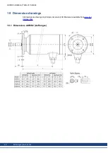
Dimension drawings can be found in chapter "Dimension Drawings" (
13.1 Important Notes
Only qualified staff with knowledge of mechanical engineering are permitted to assemble the
motor.
l
Protect motor and cable from unacceptable stresses. During transport and handling no
components must be damaged. Avoid scratches on the stainless steel surface.
l
Shaft end upwards mounting is not allowed in hygienic applications.
l
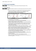
Basic styles for flange mounting according to EN 60034-7:
Flange mounting (flange types Ax, Bx)
Face mounting (flange types Cx, Dx)
allowed: B5
allowed: B14, V18
l
Use o-ring (part of delivery) for face or flange interface at motor mounting.
l
Use sealed screws for motor mounting.
l
If the shaft is exposed, cover the shaft center hole with sealed screw.
l
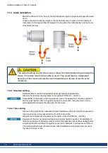
Mount the cable exit in the “down” or lower hemisphere region to promote drainage after
washdown. Add a strain relief to the cable if necessary.
l
Ensure an unhindered ventilation of the motors and observe the permissible ambient and
flange temperatures. For ambient temperatures above 40°C please consult our appli-
cations department beforehand. Ensure that there is adequate heat transfer in the sur-
roundings and the motor flange.
l
Motor flange and shaft are especially vulnerable during storage and assembly — so avoid
brute force. It is important to use the locking thread which is provided to tighten up cou-
plings, gear wheels or pulley wheels and warm up the drive components, where possible.
Blows or the use of force will lead to damage to the bearings and the shaft.
l
Wherever possible, use only backlash-free, frictionally-locking collets or couplings.
Ensure correct alignment of the couplings. A displacement will cause unacceptable vibra-
tion and the destruction of the bearings and the coupling.
l
In all cases, do not create a mechanically constrained motor shaft mounting by using a
rigid coupling with additional external bearings (e.g. in a gearbox).
l
Avoid axial loads on the motor shaft, as far as possible. Axial loading significantly short-
ens the life of the motor.
l
Check the compliance to the permitted radial and axial forces F
R
and F
A
.
When you use a toothed belt drive, the minimal permitted diameter of the pinion e.g. fol-
lows from the equation:
.
AKMH Installation | Table of Contents
46
Kollmorgen | March 2014
Содержание AKMH2
Страница 62: ...18 4 Dimensions AKMH3 Ax flanges AKMH Installation Table of Contents 62 Kollmorgen March 2014...
Страница 64: ...18 7 Dimensions AKMH4 Ax flanges AKMH Installation Table of Contents 64 Kollmorgen March 2014...
Страница 66: ...18 10 Dimensions AKMH5 Ax flanges AKMH Installation Table of Contents 66 Kollmorgen March 2014...
Страница 68: ...18 13 Dimensions AKMH6 Ax flanges AKMH Installation Table of Contents 68 Kollmorgen March 2014...
Страница 71: ...19 3 Hygienic Standards Declaration of Conformity AKMH Installation Table of Contents Kollmorgen March 2014 71...
Страница 73: ...AKMH Installation Kollmorgen March 2014 73...
Страница 74: ...74 Kollmorgen March 2014 AKMH Installation...

