7.16.3 Use as directed
The STO function is exclusively intended to provide a functional safe stop of the motion sys-
tem. To achieve this functional safety, the wiring of the safety circuits must meet the safety
requirements of IEC 60204, ISO 12100 and ISO 13849.
Use the following functional sequence when the STO function is used:
1. Brake the drive in a controlled manner (speed setpoint = 0 V).
2. When speed = 0 rpm, disable the drive (enable = 0 V).
3. If a suspended load is present, block the drive mechanically.
4. Activate the STO function.
7.16.4 Prohibited use
The STO function must not be used if the drive is to be made inactive for:
Cleaning, maintenance and repair operations, long inoperative periods. In such cases, the
entire system should be disconnected from the supply and secured (main switch).
Emergency-Off situations. In an Emergency-Off situation, the main contactor is switched
off (by the Emergency-Off button).
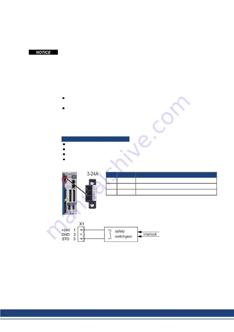
7.16.5 Technical data and pinout
AKD-x003 up to AKD-x024
Input STO (X1)
Reference ground is GND
24 V ±10%, 45 mA
Galvanic isolation for 250 VDC
Reaction time < 10 ms
Pin
Signal
Description
1
+24
+24 VDC Auxiliary voltage
2
GND
24V Supply GND
3
STO
STO enable (Safe Torque Off)
AKD Installation | 7 Technical description and data
Kollmorgen | kdn.kollmorgen.com | October 2017
57
Содержание AKD series
Страница 162: ...AKD Installation 9 Electrical Installation Wiring diagram X24 162 Kollmorgen kdn kollmorgen com October 2017 ...
Страница 179: ...9 20 6 CAN Bus Wiring AKD Installation 9 Electrical Installation Kollmorgen kdn kollmorgen com October 2017 179 ...
Страница 214: ... AKD Installation 11 Index 214 Kollmorgen kdn kollmorgen com October 2017 ...


