121
120
10
A
5
,
4
5
,
4
5
,
4
5
,
4
5
,
4
5
,
4
5
,
4
5
,
4
5
,
4
B
7
1
,
0
x
4
0
2
,
0
x
4
1
4
1
,
0
x
5
2
2
,
0
x
4
1
4
1
,
0
x
5
9
5
1
,
0
x
5
0
5
1
,
0
x
5
6
6
1
,
0
x
5
5
6
1
,
0
x
5
5
,
0
6
,
0
8
,
0
6
,
0
8
,
0
5
,
0
8
,
0
5
,
0
8
,
0
aaaaa
°
0
6
1
°
0
6
1
°
5
5
1
°
0
6
1
°
5
4
1
°
0
6
1
°
0
6
1
°
0
6
1
°
5
5
1
÷
0
1
,
0
5
1
,
0
÷
0
1
,
0
5
1
,
0
÷
5
7
1
,
0
5
2
2
,
0
÷
5
2
1
,
0
5
7
1
,
0
÷
5
7
1
,
0
5
2
2
,
0
÷
5
7
3
,
0
5
2
4
,
0
÷
5
7
3
,
0
5
2
4
,
0
÷
5
7
3
,
0
5
2
4
,
0
÷
5
7
3
,
0
5
2
4
,
0
C
³
m
m
6
3
,
0
³
m
m
6
3
,
0
³
m
m
0
³
m
m
6
3
,
0
³
m
m
0
³
m
m
9
1
,
0
³
m
m
0
³
m
m
9
1
,
0
³
m
m
0
4
±
4
1
2
4
±
4
1
2
6
±
0
4
2
4
±
4
1
2
6
±
0
4
2
4
±
0
0
2
4
±
9
5
2
4
±
0
0
2
6
±
0
4
2
- 59 -
FUEL SYSTEM
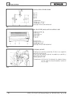
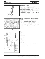
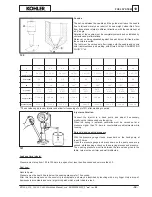
Leakage time (waste)
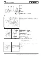
Pressure must drop from 150 to 100 bars in a span of not less than 8 seconds and not more than 30.
Seat seal
Nozzle tip wet.
Pressure must be kept 20 bars below the opening pressure for 10 seconds.
After this time, dampness on the nozzle tip is acceptable, and may be identified by touching with a dry finger. Only a drop of
dampness is acceptable and not a large thick patch which would indicate a leak.
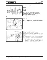
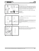
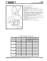
Injector calibration
Connect the injector to a hand pump and adjust if necessary,
modifying the thickness above the spring.
When the spring is replaced, calibration must be carried out at a
pressure higher than 10 bars to counterbalance adjustments while
running.
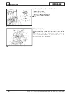
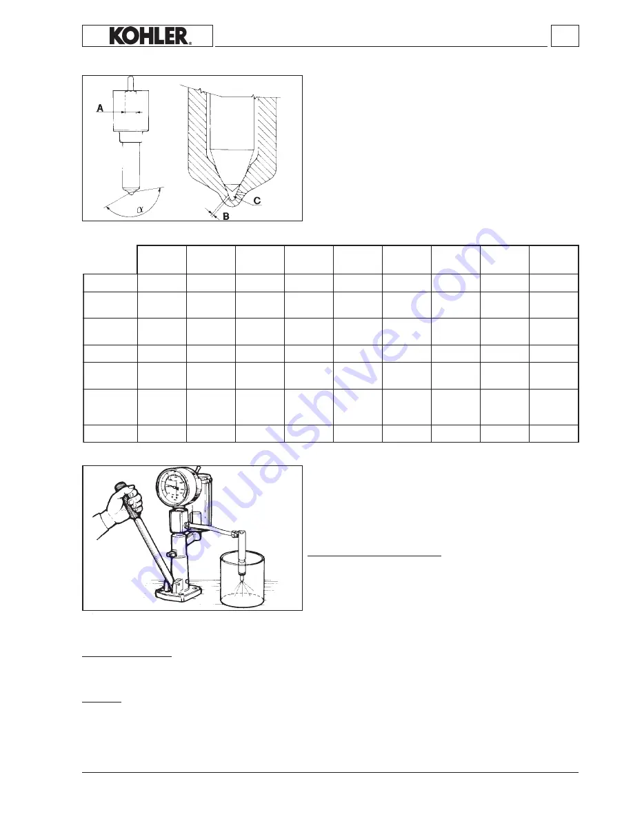
Spraying and opening pressure
With the pressure gauge closed, press hard on the hand pump at
least 10 times.
Open the pressure gauge and press down on the pump once every
second, while keeping a check on the spraying process and pressure.
The opening pressure must lie between the two values given in the
table. Jets must be uniform and well distributed.
*
These values apply to new injector and allow for loosening of up to10% after breaking-in period
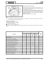
Nozzles
The set-up between the needle and the guide must leave the needle
free to fall and merely as a result of its own weight, when lifted 7mm
from its seat and rotated in different directions, with the nozzle kept at
a 45° angle.
Rotation of the needle must be completely smooth and uninhibited by
obstacles and malformations.
Moreover, on being squeezed against its seat, it must fall freely, when
the nozzle is inverted.
The test must be carried out after rinsing both the needle and nozzle
with trichloroethane and wetting with filtered SHELL CALIBRATION
FLUID “C” oil.
n° and Ø of holes
hole lenght
pin height
sump volume
pressure (bar)*
KD 225_315_350_400_440 Workshop Manual_cod. ED0053029330_
1° ed
_ rev.
00
Содержание KD225
Страница 1: ...KD225 KD315 KD350 KD400 KD440 WORKSHOP MANUAL ...
Страница 10: ... 10 NOTE KD 225_315_350_400_440 Workshop Manual_cod ED0053029330_1 ed_ rev 00 ...
Страница 32: ...8 32 DISASSEMBLY REASSEMBLY KD 225_315_350_400_440 Workshop Manual_cod ED0053029330_1 ed_ rev 00 ...
Страница 42: ...8 42 DISASSEMBLY REASSEMBLY KD 225_315_350_400_440 Workshop Manual_cod ED0053029330_1 ed_ rev 00 ...
Страница 60: ...10 60 FUEL SYSTEM KD 225_315_350_400_440 Workshop Manual_cod ED0053029330_1 ed_ rev 00 ...

