


TP-6694
9/20
21
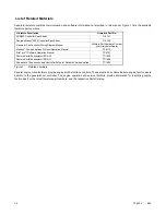
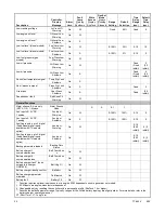
Low oil pressure
Megajector communications loss
(GM/PSI and Doosan gas-powered models only)
Metering communication loss
No coolant temperature signal
No oil pressure signal
Overcrank
Overfrequency
Overvoltage (each phase)
Run relay overload
Underfrequency
Undervoltage (each phase)
(Voltage) regulator communication loss
* Requires optional input sensors
1.2.3
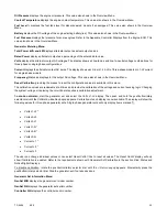
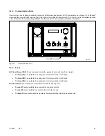
Digital Display
Press the pushbutton/rotary selector dial to turn on the controller lamps and display. The lamps and display turn off 60 minutes
after the last entry.
Note:
The APM402 controller takes about 5-10 seconds to power on.
The generator set must be running for some displays to indicate values. If the generator set is not running some values will
display zero or N/A (not available).
Some displays are engine dependent. Refer to the Appendix titled: Controller Displays from the Engine ECM.
The 12-character, 2-line backlit heated display provides generator set and engine data, system status, and fault information.
See the figure titled: Controller with Digital Display and Pushbutton/Rotary Selector Dial. The digital display shows abbreviations
in some instances. Refer to the section titled: Status Event and Fault Specifications for the abbreviations and their full
descriptions.
Note:
US/Metric Unit Display
is selectable in Generator Set System.
Note:
Display Contrast
is selectable in Generator Set System. The contrast display adjustment allows user selected resolution values
to improve digital display clarity.
Note:
After about 5 minutes of no user input (pushbutton/rotary selector dial or buttons), the menu resets to the top of the main menus
and auto-paging activates for the Overview submenus.
The main menus are listed below. Within each main menu are multiple submenus with descriptions following.
Overview
Engine Metering
Generator Metering
GenSet Information
GenSet Run Time
GenSet System
Содержание APM402
Страница 6: ...6 TP 6694 9 20 ...
Страница 16: ...16 TP 6694 9 20 ...
Страница 42: ...42 TP 6694 9 20 ...
Страница 78: ...78 TP 6694 9 20 ...
Страница 112: ...112 TP 6694 9 20 ...
Страница 120: ...120 TP 6694 9 20 ...
Страница 124: ...124 TP 6694 9 20 Figure 54 20 150 kW Permanent Magnet Single Phase Alternators ADV 5875AB 1 ...
Страница 125: ...TP 6694 9 20 125 Figure 55 20 300 kW Permanent Magnet Alternators ADV 5875AB 2 ...
Страница 126: ...126 TP 6694 9 20 Figure 56 60 IMS 300 kW Wound Exciter Field 20 300 kW 600 V Perm Magnet Alternators ADV 5875AB 3 ...
Страница 127: ...TP 6694 9 20 127 Figure 57 300 kW and Larger Pilot Excited Permanent Magnet 4M 5M 7M 10M Alternators ADV 5875AB 4 ...
Страница 128: ...128 TP 6694 9 20 ...
Страница 131: ...TP 6694 9 20 131 Figure 61 Battery Charger to Controller Connections DEC 3000 Controller ...
Страница 153: ...TP 6694 9 20 153 Figure 90 Controller Wiring Connections GM78246G 1 ...
Страница 154: ...154 TP 6694 9 20 Figure 91 Controller Wiring Connections GM78246G 2 ...
Страница 171: ......


