


TP-6694
9/20
103
3.9.3
Procedure to Drain Cooling System
For optimum protection, drain, flush, and refill the cooling system at the intervals listed in the service schedule.
Note:
Dispose of all waste materials (oil, fuel, coolant, filters, and gaskets) in an environmentally safe manner.
1. Before removing the pressure cap, stop the generator set and allow it to cool.
2. Deenergize the block heater, if equipped.
Note:
Use a rag to cover the radiator cap during removal.
3. Remove the pressure cap to prevent air pockets from restricting coolant flow through the engine block.
4. Open the radiator and/or engine block coolant drain valve(s) and allow the system to drain.
5. If the inside of the radiator has mineral deposits or the used coolant contains dirt or grease, refer to the following section,
Procedure to Flush and Clean the Cooling System. If the cooling system does not have mineral deposits, go to the following
section, Procedure to Refill the Cooling System.
3.9.4
Procedure to Flush and Clean Cooling System
Use the instructions in the engine operation manual when available to flush and clean the cooling system. Otherwise, use the
following procedure and the cooli
ng system cleaner manufacturer’s instructions.
1. Flush the cooling system with distilled or deionized water.
2. If the inside of the radiator still has mineral deposits, use a radiator cleaner to remove the remaining deposits following
the manufacturer’s instructions.
3. Drain, clean, and flush the coolant recovery tank.
3.9.5
Procedure to Refill Cooling System
See the generator set spec sheet for coolant capacity.
Note:
Do not add coolant to a hot engine. Adding coolant to a hot engine can cause the cylinder block or cylinder head to crack. Wait
until the engine has cooled.
1. Remove the pressure cap.
2. Close the radiator and/or engine block coolant drain valve(s) and tighten the cooling system hose clamps.
Note:
If possible, fill the radiator from the bottom to avoid air pockets.
3. Open the air-bleed petcocks, if equipped. Close the air-bleed petcocks when coolant begins to flow from them.
Note:
Refer to the engine operation manual for air-bleed petcock locations.
4. Fill the cooling system with the recommended genuine Kohler coolant/antifreeze mixture based on the engine
manufacturer’s recommendation.
5. Replace the pressure cap.
6. Fill the coolant recovery tank (if equipped) to the low mark.
7. Operate generator set until the thermostat opens when the upper cooling system hose warms.
8. Stop the engine and allow it to cool.
9. Check and repair any coolant leaks.
Содержание APM402
Страница 6: ...6 TP 6694 9 20 ...
Страница 16: ...16 TP 6694 9 20 ...
Страница 42: ...42 TP 6694 9 20 ...
Страница 78: ...78 TP 6694 9 20 ...
Страница 112: ...112 TP 6694 9 20 ...
Страница 120: ...120 TP 6694 9 20 ...
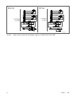
Страница 124: ...124 TP 6694 9 20 Figure 54 20 150 kW Permanent Magnet Single Phase Alternators ADV 5875AB 1 ...
Страница 125: ...TP 6694 9 20 125 Figure 55 20 300 kW Permanent Magnet Alternators ADV 5875AB 2 ...
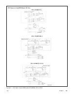
Страница 126: ...126 TP 6694 9 20 Figure 56 60 IMS 300 kW Wound Exciter Field 20 300 kW 600 V Perm Magnet Alternators ADV 5875AB 3 ...
Страница 127: ...TP 6694 9 20 127 Figure 57 300 kW and Larger Pilot Excited Permanent Magnet 4M 5M 7M 10M Alternators ADV 5875AB 4 ...
Страница 128: ...128 TP 6694 9 20 ...
Страница 131: ...TP 6694 9 20 131 Figure 61 Battery Charger to Controller Connections DEC 3000 Controller ...
Страница 153: ...TP 6694 9 20 153 Figure 90 Controller Wiring Connections GM78246G 1 ...
Страница 154: ...154 TP 6694 9 20 Figure 91 Controller Wiring Connections GM78246G 2 ...
Страница 171: ......


