- 0 -
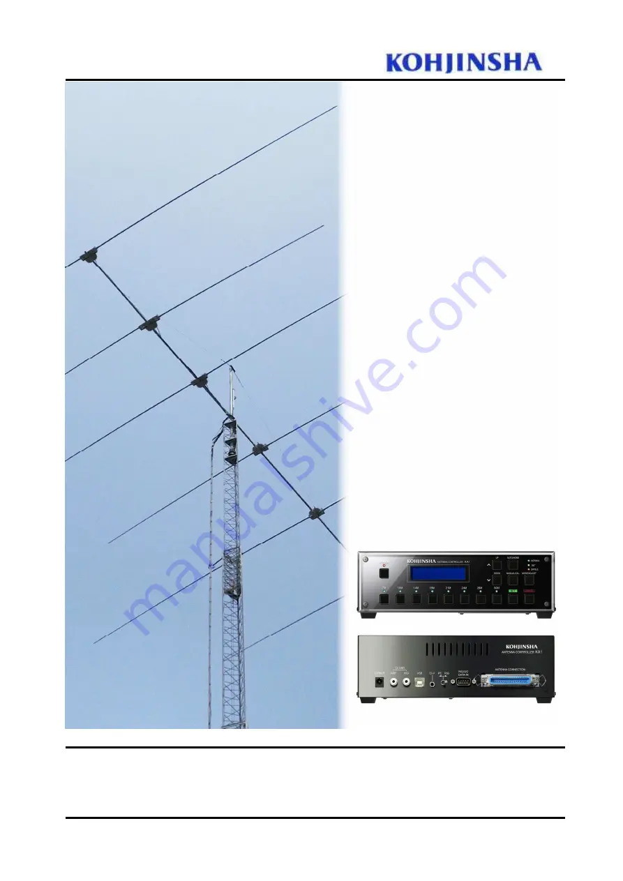
VERSA Beam
Antenna Controller
INSTRUCTION MANUAL
Please keep this manual after you read for maintenance purpose
Rev3.01 Jun. 2020
Страница 1: ... 0 VERSA Beam Antenna Controller INSTRUCTION MANUAL Please keep this manual after you read for maintenance purpose Rev3 01 Jun 2020 ...
Страница 2: ... Remote Operation 22 6 7 What You Should Keep in Mind When You Measure SWR 22 6 8 Frequency Segment Width Change 6 8 1 For Regular VERSA BEAM Frequency Segment Width Change 23 6 8 2 For VERSA Lite Frequency Segment Width 23 7 User Mode Settings 7 1 What You Can Do with User Mode 24 7 2 Start Your Controller with User Mode 26 8 Factory Default 27 9 Connecting Transceiver with Computer 9 1 Jumper Se...
Страница 3: ...uct it or do maintenance CAUTION Do not use AC adaptor or cable that doesn t come with KA1 Before installing KA1 on the tower please make and confirm Adjustable Element Unit AEU working on the ground Pull off the DC plug from the controller when you attach or remove the Amphenol connector While in operation elements are not fully out or home in between push HOME button to get all the elements home...
Страница 4: ...Element Top Element Supporting Rubber Rubber Holder Element Housing Housing Cover Housing Gasket Coaxial Connector only AEU for driven element Control Cable Connector Glass Fiber Tubing Note We named the unit assembled with to listed above AEU ...
Страница 5: ... small amount of electric current is running That makes the controller a bit warm It is not a problem or failure In case of power outage or something happen like that by turning on the power VERSA antenna itself retracts all element to HOME position and then extends elements to the original position where it was before the power turned off accidentally BAND Elements move to the each band position ...
Страница 6: ...g the beam direction to opposite side In this mode all the KA1 models work as 3 element Yagi DIPOLE KA1 has gain on both side front and back working like a dipole however it has some gain AUTO HOME AUTO Coordinate with your transceiver frequency HOME Press and Hold All the elements are wound up to the home position LCD Displays antenna settings frequency and MODE Example LCD display Your VERSA ant...
Страница 7: ...e two options of showing this information Read the following description carefully Band Frequency Display While Manual Mode is selected Band and Frequency are displayed on the LCD shown like below 7M 14M 21M 28M bands are divided into 3 segments Each pressing of BAND Button switches the segment 7M 40m 7 000MHz 40m 7 040MHz 40m 7 120MHz 10M 30m 10 100MHz 14M 20m 14 050MHz 20m 14 150MHz 20m 14 250MH...
Страница 8: ...9MHz 21 200 21 249MHz 21 350 21 399MHz 24M 24 950 24 999MHz 28M 28 000 28 049MHz 28 500 28 549MHz 29 000 29 049MHz 50M 50 100 50 149MHz 7MHz band and 10MHz band are not available for Model 203 204 205 206 Freq Region Display While Auto Mode is selected KA1 controller shows the same frequency as your transceiver shows Example If your transceiver frequency 14 195MHz you see the same number like 14 1...
Страница 9: ...band by UP DOWN button You can also change element length from the factory default and save the new settings in the controller with ADJUST on a band You can try to fine tune because it is easy to go back to the factory default settings on any band See next AUTO MANUAL mode function Figure 5 The LCD shows as above and then change to as Figure 6 Figure 6 Press UP or DOWN until you see 05 Display Typ...
Страница 10: ...See Figure 3 4 5 MANUAL CAL CALIBRATION button MANUAL button This button is used to adjust element length manually You can fine tune the antenna resonant frequency by UP DOWN button In order to get back to factory default you need to press and hold the BAND button of which you want to make the setting factory default LCD displays as below Set default OK blinking SET Write complete factory default ...
Страница 11: ...encing power outage Figure 13 In case of 18 100MHz is selected Once all the elements are retracted going back to home position in the AEU elements will start extending to the correct length for the selected band segment One of MODE LEDs turns to on from blinking tells you finishing the calibration process 4 6 CANCEL button You can cancel the immediate operation by pressing this button Figure 11 Pr...
Страница 12: ... button Press SET to determine which element length should be adjusted Each pressing UP or DOWN button let the element extend or rewind 5mm If you press and hold the button the element keeps moving until you release the button Press SET to set and save the setting You see Write complete in LCD display You can go back to the normal operation by pressing CANCEL button to abort Adjust status After yo...
Страница 13: ...u will see SET blink if you press UP or DOWN to adjust element Figure 16 Press SET to set and finish adjustment Write Complete will stop blinking Figure 17 After Figure 16 process you will see AEU name in this example it is Radiator start blinking again If you want to adjust another element use UP or DOWN to choose it Figure 18 shows appearance of LCD display when you adjust all the elements at th...
Страница 14: ...ng SPLIT mode operation KA1 controller follows only receiving frequency of some transceivers that don t have transmitting frequency output like TS950 850 HOME button Press and hold Pressing HOME button all the elements are retracted to the reels in AEU We call this status home position We strongly recommend retracting elements to home position during lighting storm Then please remove control cable...
Страница 15: ... display shown as Figure 20 are connector numbers in junction box Displayed numbers for each model are shown below Ra Radiator Ref Reflector D Director Figure 19 HOME Push SET blinks Press SET button to set Figure 20 When all the elements are retracted the above message comes on LCD display After showing this message the power will be shut off automatically While selected mode LED is blinking elem...
Страница 16: ...er may miscalculate the length AMP RCA female for linear amplifier control RIG RCA female for your transceiver TX GND output TX GND is connected to ground during transmitting and are connected inside of the controller normally Only when elements are in motion they are cut off to prevent KA1 from being damaged This function should also work to protect your linear amplifier USB Interface USB Type B ...
Страница 17: ... computer or transceiver to control VERSA Beam antenna RS 232C Interface Use RS232C straight cable to connect transceiver or computer that has RS232C interface Be sure to lock the connector after connection ANTENNA CONNECTION For Amphenol 36 pin connector supplied with control cable Be sure to lock the connector after connection NOTE Please confirm the AC adaptor is removed from the controller whe...
Страница 18: ... 28MHz length NORMAL LED blinks until extending stops LED stops blinking and keeps light on Press and hold MANUAL CAL button and press SET to go to calibration Element numbers are shown when elements are retracted to HOME position And then elements will extend to the 28MHz length LED stop blinking and keep light on when calibration is done 28MHz calibration should finish within 30 seconds At this ...
Страница 19: ...on We strongly recommend retracting all the elements during typhoon hurricane thunder storm heavy rain or blizzard We also recommend you to do calibration again after severe weather is gone If you do calibration on a certain band other bands are calibrated automatically The Higher the band you calibrate the shorter the time you need You can set automatic calibration after power on by USER setting ...
Страница 20: ...to Press SET You won t lose GAIN or Front to Back ratio because all the elements moves with coordinating the factory default data if you choose All How to Adjust 2 In case you couldn t t have good result by following How to Adjust 1 we would like you to try this Choose MANUAL mode and select a band which you want to adjust Set your transceiver frequency as same frequency as the controller shows Go...
Страница 21: ... Mode and Snow Mode At any frequency position the controller switches from normal mode to Rain Mode by pressing not press and hold just press SET button From Rain Mode one press of SET button let the controller work as Snow Mode In both cases you can see R for Rain Mode S for Snow Mode in LCD display The amount of frequency shift should be set for both Rain and Snow Mode beforehand Figure 24 Displ...
Страница 22: ...es until 10 RainShift shows up You can set frequency shift amout in 10 17 for Rain Mode shift and 20 27 for Snow Mode shift for each bands Use AUTO HOME and MANU CAL buttons to select shift amount Once you finish selecting shift amount press SET button then controller automatically start writing data The power will also be off automatically after the job is done Figure 25 Example A Setting 15m Rai...
Страница 23: ...c calibration Note If the elements are retracted to HOME position automatic calibration won t start 6 7 What You Should Keep in Mind When You Measure SWR When you measure SWR Make your tower the highest if your tower is a crank up tower Do not do it on the day of heavy rain snow or windy Choose the antenna direction to keep elements as far away as possible from trees wires or buildings If the elem...
Страница 24: ...Figure 30 to 31 Pressing and holding UP bottun make the controller to original 40KHz step mode Figure 30 regular 40KHz Step Figure 31 20KHz Step MHz means 40KHz step mhz means 20KHz step 6 8 2 Lite Model 203L 403L VERSA Lite works as same as described above for regular VERSA antenna You can set up using as same procedure as regular VERSA antenna Refer Figure 30 to 31 7MHz 20KHz 10KHz step 10MHz 14...
Страница 25: ...them for your system 04 ICOM RX ADRS If needed choose one of the addresses that are mapped for ICOM equipments 05 FreqDisp Form Choose your favorite display format from Band Freq or Freq Region 06 Tracking Delay KA1 elements move in accordance with your transceiver VFO frequency being driven by step motors every 50 KHz 400series every 40 KHz on 7MHz You hear step motor noise at the above moment Th...
Страница 26: ...f you select below 7MHz band with 400 series KA1 retracts all the elements to home position by this setting LCD display and its function 000 Not Auto HOME No automatic retraction 001 Auto HOME Automatic retraction 10 17 Rain Mode 20 27 Snow Mode How to Set up Frequency Shift in the Rain Snow Mode You can setup frequency shift amount in the Rain or Snow mode You can follow the same procedure that i...
Страница 27: ...See Figure 33 Figure 33 Each time pressing UP DOWN button the display switches like Baud Rate Stop Bit and etc In order to select your transceiver model press AUTO HOME or MANUAL CAL when you see Exciter Type on the LCD display Don t press SET yet Following above operation you need to set up Baud Rate and others After you set up all the settings here press SET You will see Write Complete on the LC...
Страница 28: ...ld each BAND button Press and hold POWER to turn off the power Press and holding 7M button press POWER button Figure 35 User mode appears and then Figure 36 is shown Pressing 7M button press SET button at Figure 36 state Figure 37 appears while controller is getting back to factory default setting When factory default is set you see Figure 38 The power is automatically shut off Press POWER button ...
Страница 29: ...ure 36 Press and holding 7M button press and hold SET button when you see this screen Figure 37 This is showing the software is getting back to factory default settings When the five digit counter becomes 0 the controller setting is factory default Figure 38 When the work is done you see this screen The power is shut off automatically Figure 39 Press POWER button to restart the controller then thi...
Страница 30: ... and computer Please look at the drawing below Remove two screws and take off the cover You will be able to see controller board Note Be sure to remove power supply from your controller before doing this work DIP switches are lined up as shown in the picture After you finish DIP switch settings install the cover you removed Please don t connect power supply before installing the cover ...
Страница 31: ...000 FT1000MP MK V KENWOOD TS990 TS590 TS2000 TS480 TS870 YAESU FT920 ELECRAFT K2 K3 JRC JST145 JST245 Controller interface RS232C D sub 9pin female Rig interface RS232C D sub 9pin female RS232C D sub 9pin male RS232C D sub 25pin male Set DIP switches shown as Figure 40 Figure 40 ...
Страница 32: ... 31 9 1 2 ICOM All ICOM transceivers that have CI V interface Controller interface CI V 3 5mm mini jack 2p Rig interface REMOTE 3 5mm mini jack 2p Set DIP switches shown as Figure 35 Figure 41 ...
Страница 33: ... 32 9 1 3 YAESU Transceivers FT1000 FT1021 Controller interface RS232C D sub 9pin female Rig interface DIN6 pin male Set DIP switches shown as Figure 42 Figure 42 ...
Страница 34: ... 33 9 1 4 KENWOOD Transceivers TS950 TS850 Controller interface RS232C D sub9 pin female Rig interface DIN6 pin male Set DIP switches shown as Figure 43 Figure 43 ...
Страница 35: ...e switch PC RIG on the controller rear panel toward PC side BEFORE turning power on Not only you can control the transceiver and controller from your computer screen but also the computer can import band mode data from your transceiver You won t be able to set KA1 frequency under this setup from your transceiver unless you have started logging software When you use logging software you may need to...
Страница 36: ...0 FT DX 5000 FT 2000 Change 03 Logging Soft set up to select your logging software For HAMLOG select FT2000 9000 for input setting and set timer command 0 For HAMLOG setup you need to select KENWOOD Tracking function may not work properly because of logging software setups KENWO OD TS 950 TS 850 Set 00 Exciter Type 007 TS950 850_AI Choose your logging software by selecting setting of 03 Logging So...
Страница 37: ...ed FT 1000D FT 1021 00 Exciter Type 010 FT 1000 01 Baud Rate 004 4800 Fixed 02 Stop bit 02 2 Stop bit Fixed KENWOOD TS 990 TS 590 TS 2000 TS 480 TS 870 等 00 Exciter Type 005 KWD K2 K3_AI 01 Baud Rate 004 4800 Same baud rate as your radio interface 02 Stop bit 01 1 Stop bit TS 950 TS 850 00 Exciter Type 006 TS950 850_IF 007 TS950 850_AI 1 01 Baud Rate 004 4800 Fixed 02 Stop bit 02 2 Stop bit Fixed ...
Страница 38: ...d setting but some logging soft prefer 004 Older KENWOOD model thanTS 870 It may happen on TS 950SDX or TS 850 that the output power is reduced to half for about 16 seconds during transmitting In this case set 007 TS950 850 AI However if you set as above memory frequency tracking is disabled JST 145 JST 245 not used FT 1000D FT 1021 FT 767 not used not used not used FTDX101 FT991 FT2000 FTDX9000 F...
Страница 39: ... from VERSA Beam antenna Turn PC RIG to RIG ICOM 000 Not Use You can leave there as Not Use YAESU For HAMLOG ZLOG Logger32 and Mixw2 06 FTC Logger For CT 007 FTC LoggerCT KENWOOD 000 Not Use For HAMLOG Zlog and CT Set up 00 Exciter Type 005 KWD K2 K3_AI or 007 TS950 TS850_AI Notice If you choose 1 to control your transceiver and VERSA Beam antenna from your computer you need to activate your loggi...
Страница 40: ... transceiver frequency 001 Freq Region Displaying Freq Region on LCD Displaying frequency region all the time whatever mode is selected 06 Tracking Delay You can set tracking time with your transceiver 000 0 sec 001 3 sec 002 6 sec 003 9 sec 004 12 sec 005 15 sec 07 Auto CAL You can select automatic or non automatic calibration 000 No Auto CAL No automatic calibration 001 Auto CAL Calibration star...
Страница 41: ...nnected securely Wiring in junction box is not connected securely Check connections and make sure connection is securely done 17 High SWR Elements aren t retracted at HOME POSITION Each junction cable is not connected securely Control cable is not connected securely Wiring in junction box is not connected securely or connected wrong Element length is not proper Check connections and make sure conn...
Страница 42: ...P11 5 5 6 Antenna mode change NORMAL 180 DIPOLE Press MODE ADJUST P6 P13 5 7 P15 5 8 5 9 7 Retract all the elements Press and hold AUTO HOM Press SET P15 P16 8 Element length calibration Press and hold MANUAL CAL Press SET P6 P11 5 5 9 Manually change element length Press UP DOWN P6 P11 5 3 10 Element length adjustment Press and hold MODE ADJUST Press SET and then use UP DOWN button to choose elem...
Страница 43: ...d be either AUTO or MANUAL mode 17 Rain Mode Press SET button P22 SET button works as toggle switch Each press switches Rain Snow Rain 18 Snow Mode Press SET button P22 19 Back to normal mode from Rain or Snow mode Press CANCEL P22 20 Setting up shift amount for Rain Mode User mode Setup in the user mode P23 21 Setting up shift amount for Snow Mode User mode Setup in the user mode P23 22 Setting u...
Страница 44: ...A Beam antenna should work in accordance with the operation described in this instructions manual Service If it is ever necessary to return VERSA Beam antenna double check by yourself or consult a Kohjinsha specialist to make sure what part of VERSA Beam antenna is wrong specifically Then you can avoid shipping whole stuff to our factory Contacts Email info kojinsha jp NOT Kohjinsha but kojinsha T...