background image

8

Initialization Method


  43 

8.  Initialization Method 


The setting procedures in this guide are based on the factory default settings.   

Some settings may not be applicable unless you use the devices with the factory default 

settings.   


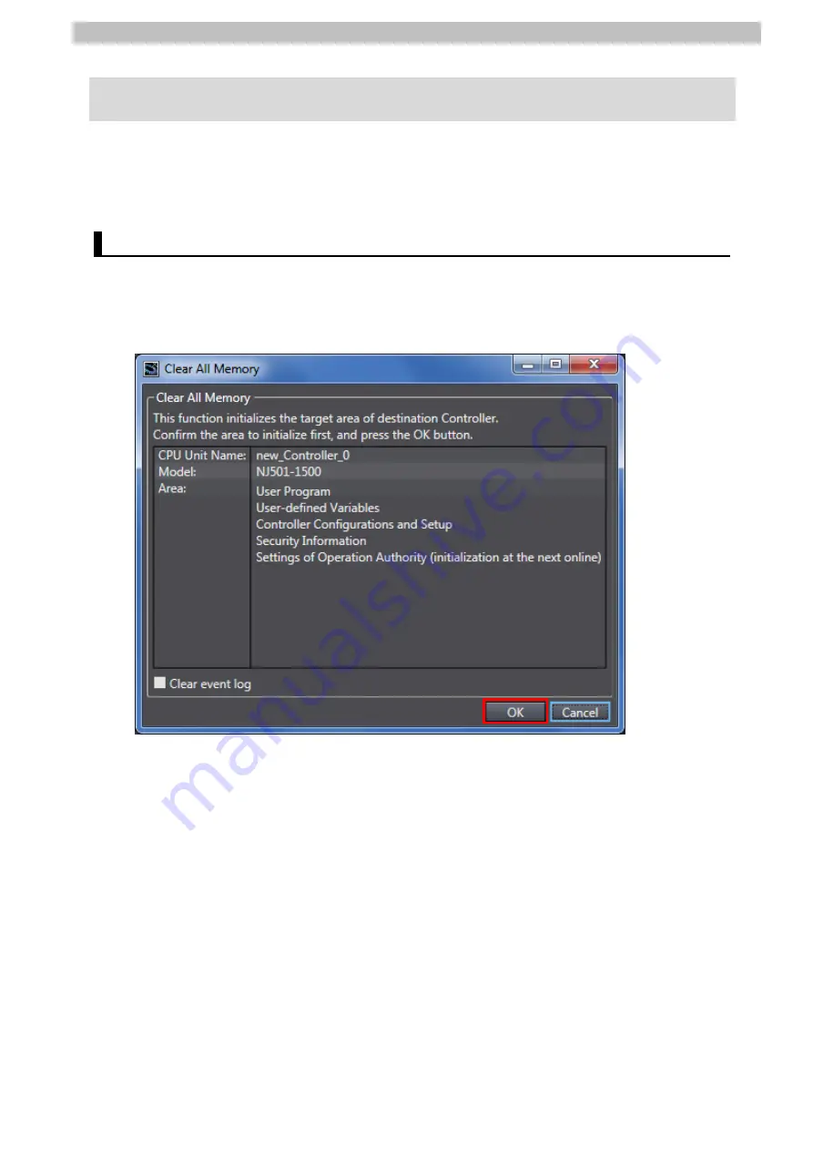
8.1.  Initializing a Controller 

To initialize the settings of a Controller, it is necessary to initialize a CPU Unit.   

Change the operating mode of Controller to PROGRAM mode and select 

Clear All Memory


from the Controller Menu in Sysmac Studio. The Clear All Memory Dialog Box is displayed. 

Check the contents and click 

OK

.   


Содержание F Series

Страница 1: ...Machine Automation Controller NJ NX series EtherNet IPT M Connection Guide KOGANEI CORPORATION Manifold Solenoid Valve F Series P691 E1 01 ...

Страница 2: ...r countries ODVA and EtherNet IPTM are trademarks of ODVA EtherCAT is registered trademark and patented technology licensed by Beckhoff Automation GmbH Germany Sysmac is a trademark or registered trademark of OMRON Corporation in Japan and other countries for OMRON factory automation products Company names and product names in this guide are the trademarks or registered trademarks of their respect...

Страница 3: ...rNet IP Settings 8 6 1 Parameters 8 6 2 Global Variable 9 6 3 Tag Set 9 7 EtherNet IP Connection Procedure 10 7 1 Work Flow 10 7 2 KOGANEI Manifold Solenoid Valve Setup 12 7 3 Controller Setup 19 7 4 Network Settings 28 7 5 EtherNet IP Communication Status Check 38 8 Initialization Method 43 8 1 Initializing a Controller 43 8 2 Initializing a KOGANEI Manifold Solenoid Valve 44 9 Revision History 4...

Страница 4: ...MRON W535 NX701 17 NX701 16 NX series CPU Unit Hardware User s Manual OMRON W578 NX1P2 11 NX1P2 10 NX1P2 90 NX series NX1P2 CPU Unit Hardware User s Manual OMRON W501 NX701 17 NX701 16 NX1P2 11 NX1P2 10 NX1P2 90 NJ501 5 NJ501 4 NJ501 3 NJ301 12 NJ301 11 NJ101 10 NJ101 90 NJ NX series CPU Unit Software User s Manual OMRON W506 NJ NX series CPU Unit Built in EtherNet IPTM Port User s Manual OMRON W5...

Страница 5: ... a tag data link Connection A connection is used to exchange data as a unit within which data concurrency is maintained The connection consists of tags or tag sets Creating a concurrent tag data link between specified nodes is called a connection establishment When a connection is established tags or tag sets that configure the connection are exchanged between specified nodes concurrently Connecti...

Страница 6: ... in this guide is current as of October 2017 It is subject to change for improvement without notice The following notations are used in this guide Indicates a potentially hazardous situation which if not avoided may result in minor or moderate injury or may result in serious injury or death Additionally there may be significant property damage Indicates a potentially hazardous situation which if n...

Страница 7: ...red to as the Manifold Solenoid Valve to an OMRON NJ NX series Machine Automation Controller hereinafter referred to as the Controller via EtherNet IP and for checking their communication status Refer to Section 6 EtherNet IP Settings and Section 7 EtherNet IP Connection Procedure to understand setting methods and key points to operate EtherNet IP tag data links ...

Страница 8: ...ribe the procedures for connecting the devices and checking their connection You cannot use devices with versions lower than the versions listed in 5 2 To use the above devices with models not listed in 5 2 or versions higher than those listed in 5 2 check the differences in the specifications by referring to the manuals before operating the devices Additional Information This guide describes the ...

Страница 9: ...sted pair cable of Ethernet category 5 or higher KOGANEI EtherNet IP Compliant Serial Transmission Block YS7M3L Ver 1 1 KOGANEI Manifold Solenoid Valve F10M16SJ KOGANEI EDS file for 32 outputs YS7M3_v1_1 eds Ver 1 0 KOGANEI icon file YS7Mn ico Power supply for Manifold Solenoid Valve 24 VDC Rockwell Automation Inc BOOTP DHCP Tool BootP DHCP EtherNet IP Tool Ver 3 01 00 If you use a Serial Transmis...

Страница 10: ...upply specifications for the Manifold Solenoid Valve refer to the EtherNet IP Compliant Serial Transmission Compatible Manifold User s Manual BK HV045 Additional Information The system configuration in this guide uses USB for the connection between the personal computer and the Controller For information on how to install the USB driver refer to A 1 Driver Installation for Direct USB Cable Connect...

Страница 11: ...arameters The parameters set in this guide are shown below 6 1 1 EtherNet IP Communications Settings The parameters required to connect the Controller and the Manifold Solenoid Valve via EtherNet IP are shown below Setting item Controller Node 1 Manifold Solenoid Valve Node 2 IP address 192 168 250 1 192 168 250 2 Subnet mask 255 255 255 0 255 255 255 0 ...

Страница 12: ...old Solenoid Valve refer to 7 Relationship between I O data allocation and solenoid valves of the EtherNet IP Compliant Serial Transmission Compatible Manifold User s Manual BK HV045 Additional Information With Sysmac Studio two methods can be used to specify an array for a data type After specifying 1 is converted to 2 and the data type is always displayed as 2 1 BOOL 32 2 ARRAY 0 31 OF BOOL In t...

Страница 13: ...nifold Solenoid Valve 7 2 2 Parameter Settings Set the IP address of the Manifold Solenoid Valve 7 3 Controller Setup Set up the Controller 7 3 1 IP Address Settings Start Sysmac Studio and set the IP address of the Controller 7 3 2 Setting Global Variables Set a global variable to use for tag data links and create and export a CSV file in order to use as a tag with Network Configurator 7 3 3 Tran...

Страница 14: ...Transferring the Tag Data Link Parameters Transfer the tag data link parameters to the Controller 7 5 EtherNet IP Communication Status Check Confirm that the EtherNet IP tag data links perform normally 7 5 1 Checking the Connection Status Check the connection status of the EtherNet IP network 7 5 2 Checking Sent Data Check that correct data is sent ...

Страница 15: ...e position of the connectors by referring to the figure on the right Power supply communication and FG sections 3 Connect Switching hub and Communication connector L A IN on Manifold Solenoid Valve with a LAN cable Connect Switching hub and Personal computer with a LAN cable 4 Connect Power supply for Manifold Solenoid Valve to Power supply connector PWR on Manifold Solenoid Valve For details on p...

Страница 16: ...7 EtherNet IP Connection Procedure 13 5 Connect Switching hub power supply to Switching hub Power supply for Manifold Solenoid Valve Switching hub Switching hub power supply ...

Страница 17: ...al computer as shown below IP address 192 168 250 10 Subnet mask 255 255 255 0 It is necessary to set the IP address of Personal computer to 192 168 250 so that the IP address of Manifold Solenoid Valve can be set to 192 168 250 2 The IP address set in this guide is 192 168 250 10 Screenshot of Windows network settings 3 Check the positions of LEDs and Host address setting switch by referring to t...

Страница 18: ...hing hub is OFF 6 Start BOOTP DHCP Tool on Personal computer 7 Select Network Settings from the Tools Menu 8 The Network Settings Dialog Box is displayed Enter the subnet mask in the Subnet Field Subnet 255 255 255 0 Click OK Power supply for Manifold Solenoid Valve Switching hub Switching hub power supply ...

Страница 19: ... information on how to restore the settings of Manifold Solenoid Valve refer to Section 8 Initialization Method 10 With BOOTP DHCP Tool the DHCP request sent by Manifold Solenoid Valve is displayed in the Discovery History Field as shown in the figure on the right Double click the DHCP request If Manifold Solenoid Valve stops sending continuous DHCP requests due to a timeout turn OFF Manifold Sole...

Страница 20: ... Check that after a few seconds the IP address is displayed in the IP Address Column of the Discovery History Field as shown on the right 14 Right click the row that displays the added IP address of Manifold Solenoid Valve in the Entered Relations Field Select Disable BOOTP DHCP from the menu The IP address is assigned to Manifold Solenoid Valve ...

Страница 21: ...ors and warnings Field at the bottom of the screen Disable DHCP Command successful The message indicates that the IP address is correctly assigned to Manifold Solenoid Valve 16 Exit BOOTP DHCP Tool The dialog box on the right is displayed Check the contents and click No 17 Turn OFF Manifold Solenoid Valve and Switching hub ...

Страница 22: ... IP port PORT1 on Controller and connect a USB cable to the peripheral USB port As shown in 5 2 Device Configuration connect Personal computer and Switching hub to Controller 2 Start Sysmac Studio If the User Account Control Dialog Box is displayed at start make a selection to start Sysmac Studio 3 Sysmac Studio starts Click New Project Power supply for Manifold Solenoid Valve LAN cable Switching ...

Страница 23: ...from the pull down list of Version The version 1 14 is used in this guide 5 Click Create 6 The New Project is displayed The following panes are displayed in this window Left Multiview Explorer Top right Toolbox Bottom right Controller Status Pane Top middle Edit Pane The following tabs are displayed in the bottom middle of this window Output Tab Page Build Tab Page Controller Status Pane Toolbox E...

Страница 24: ...Settings under Configurations and Setup Controller Setup in the Multiview Explorer 8 The Built in EtherNet IP Port Settings Tab Page is displayed in the Edit Pane Check that the following settings are made in the IP Address Field IP address 192 168 250 1 Subnet mask 255 255 255 0 ...

Страница 25: ...b Page is displayed in the Edit Pane Click on a space in the Name Column to enter a new variable Enter EIP002_OUT in the Name Column Enter BOOL 32 in the Data Type Column After entering check that the data type changes to ARRAY 0 31 OF BOOL Select Output from the pull down list of Network Publish 3 Create a tag setting file to use with Network Configurator by following the steps below Select Expor...

Страница 26: ... the steps below Double click Task Settings under Configurations and Setup in the Multiview Explorer The Task Settings Tab Page is displayed in the Edit Pane Click VAR 6 Click the Button to add the global variable set in step 2 to the Variable to be refreshed Column An entry is displayed allowing you to specify the variable Click in the entry cell of the Variable to be refreshed Column to open the...

Страница 27: ...data device variables or values in memory used for CJ series Units Always confirm safety at the destination node before you transfer the project data 1 Turn ON Controller 2 Select Check All Programs from the Project Menu 3 The Build Tab Page is displayed Check that 0 Errors and 0 Warnings are displayed 4 Select Rebuild Controller from the Project Menu 5 The dialog box on the right is displayed Che...

Страница 28: ...lick Yes The contents of the dialog box vary depending on the status of Controller Check the contents and click on an appropriate button to proceed with the processing 10 When an online connection is established a yellow bar is displayed under the toolbar Additional Information For details on the online connections to the Controller refer to Section 6 Online Connections to a Controller of the Sysm...

Страница 29: ...een is displayed stating Synchronizing The dialog box on the right is displayed Confirm that there is no problem and click No Do not return to RUN mode 14 Check that the synchronized data is displayed with the color specified by Synchronized and that a message is displayed stating The synchronization process successfully finished Confirm that there is no problem and click Close When the Sysmac Stu...

Страница 30: ...ode is displayed If the operating mode of Controller is RUN mode change to PROGRAM mode by referring to step 16 16 Select Mode PROGRAM Mode from the Controller Menu The dialog box on the right is displayed Confirm that there is no problem and click Yes The operating mode of Controller displayed in the Controller Status Pane changes to PROGRAM mode ...

Страница 31: ...EDS file you must select Run as administrator as described in step 1 above to start Network Configurator Otherwise if you login with other user accounts the following operations listed in the EDS File Menu are not applied due to user management for Windows security functions EDS File Menu Install Create Delete and Creating EDS Index Files 2 Network Configurator starts The following panes are displ...

Страница 32: ...If the dialog box on the right is displayed check the contents and click Yes If the icon file and the EDS file are stored in the same folder the icon file is automatically installed and the dialog boxes in steps 5 and 6 are not displayed Go to step 7 6 Select YS7Mn ico icon file to install Click Open 7 Check that the device is added to the Hardware List It indicates that the EDS file is properly i...

Страница 33: ...ing the following steps If they are not connected turn OFF each of the devices and then connect the LAN cables 1 Turn ON Manifold Solenoid Valve and Switching hub 2 Select Select Interface NJ NX Series USB Port from the Option Menu 3 Select Connect from the Network Menu 4 The Select Connect Network Port Dialog Box is displayed Select TCP 2 Click OK 5 The Select Connected Network Dialog Box is disp...

Страница 34: ...ontroller cannot be established check the cable connection Or return to step 1 check the settings and repeat each step For details refer to 7 2 8 Connecting the Network Configurator to the Network of the NJ NX series CPU Unit Built in EtherNet IPTM Port User s Manual Cat No W506 7 Select Upload from the Network Menu to upload device parameters from the network 8 The dialog box on the right is disp...

Страница 35: ...resses The displayed address varies with the status of Network Configurator 10 The device parameters are uploaded After completing the upload the dialog box on the right is displayed Check the contents and click OK 11 Check that the uploaded nodes with the following IP addresses are configured in the Network Configuration Pane Controller Node 1 IP address 192 168 250 1 Manifold Solenoid Valve Node...

Страница 36: ...or right click the device icon of Controller Node 1 and select Parameter Edit 2 The Edit Device Parameters Dialog Box is displayed Select the Tag Sets Tab 3 The Tag Sets Tab Page is displayed Select Import from File from the To From File Button 4 The Import Tag Tag Set Dialog Box is displayed Select EIP002 csv and click Open EIP002 csv is the file created in step 4 of 7 3 2 Setting Global Variable...

Страница 37: ...onfirm that there is no problem and click Yes The tag name listed in the first row is used as a tag set name when creating tag sets automatically If you prefer to manually set a tag set name and edit a registered tag set click No 7 Select the Out Produce Tab on the Tag Sets Tab Page of the Edit Device Parameters Dialog Box Check that EIP002_OUT is registered as a tag set ...

Страница 38: ...ce Parameters Dialog Box Select 192 168 250 2 in the Unregister Device List and click 2 192 168 250 2 is registered in the Register Device List Select 192 168 250 2 and click New 3 The Edit Connection Dialog Box is displayed Select Exclusive Owner from the pull down list of Connection I O Type Set the values listed in the following table in the Originator Device and Target Device Fields ...

Страница 39: ...4 Byte 4 Check that the settings are correct Click Regist 5 The Edit Connection Dialog Box is displayed again Do not enter any values but simply click Close 6 The Edit Device Parameters Dialog Box is displayed again Check that the connection set for 192 168 250 2 is registered Click OK 7 The registered IP address is displayed under the device icon of Manifold Solenoid Valve Node 2 in the Network C...

Страница 40: ...device icon of Controller Node 1 in the Network Configuration Pane and select Parameter Download from the menu 2 The dialog box on the right is displayed Confirm that there is no problem and click Yes 3 The tag data link parameters are downloaded from Network Configurator to Controller 4 The dialog box on the right is displayed Check the contents and click OK ...

Страница 41: ...RR Not lit LINK ACT Yellow flashing Flashing while packets are being sent and received The NX series Controllers also have the same LED indicator status 2 Check the LED indicators on Manifold Solenoid Valve The LED indicators in normal status are as follows Sys Run Sys Rdy Green lit MS Green lit NS Green lit L A OUT Not lit L A IN Green lit 3 The normal performance of tag data links can be confirm...

Страница 42: ...ally when the same check boxes are selected as shown on the right Click Close 5 Select Disconnect from the Network Menu to go offline 6 Check that the color of the network connection icon changes from blue to gray as shown on the right It indicates offline 7 Select Exit from the File Menu to close Network Configurator Number Node number Blue Connection normal ...

Страница 43: ...rmation dialog box is displayed asking whether to save the parameters in a network configuration file Confirm that there is no problem and click No If you prefer to save the parameters in a network configuration file click Yes to save the parameters ...

Страница 44: ...make sure to complete all the steps and make the output of the Manifold Solenoid Valve safe If you change the variable values on a Watch Tab Page when Sysmac Studio is online with the CPU Unit the devices connected to Output Units may operate regardless of the operating mode of the CPU Unit Always ensure safety before you change the variable values on a Watch Tab Page when Sysmac Studio is online ...

Страница 45: ...he Modify Column for EIP002_ OUT 0 The online value of EIP002_ OUT 0 changes to True 7 Check that Solenoid No 1 LED on Manifold Solenoid Valve is lit as shown on the right You can see that the data is correctly sent and that Solenoid No 1 output is ON 8 Click FALSE in the Modify Column for EIP002_ OUT 0 The online value of EIP002_OUT 0 changes to False 9 Check that Solenoid No 1 LED on Manifold So...

Страница 46: ...s you use the devices with the factory default settings 8 1 Initializing a Controller To initialize the settings of a Controller it is necessary to initialize a CPU Unit Change the operating mode of Controller to PROGRAM mode and select Clear All Memory from the Controller Menu in Sysmac Studio The Clear All Memory Dialog Box is displayed Check the contents and click OK ...

Страница 47: ...an example of the IP address Set the IP address of your personal computer to 192 168 0 the first 3 octets of which must be the same as the IP address of Manifold Solenoid Valve 192 168 0 10 is given as an example of the IP address 2 Start Network Configurator on your personal computer Select Select Interface Ethernet I F from the Option Menu Select Connect from the Network Menu to connect to the n...

Страница 48: ...9 Revision History 45 9 Revision History Revision code Date of revision Description of revision 01 January 31 2018 First edition ...

Страница 49: ...46 ...

Страница 50: ...2018 0118 0118 P691 E1 01 ...

Отзывы: