MDC-7000/7900 Series
Chapter 3 Installation method
0092669002-07
3-3
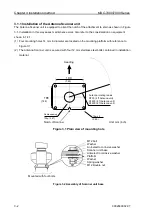
3.1.2 Mounting the Antenna
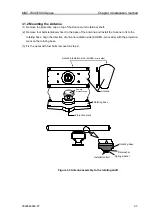
(1) Remove the protective cap on top of the Scanner unit rotational shaft.
(2) Remove four bolts tentatively fixed to the base of the antenna and install the Scanner unit to the
rotating base. Align the direction of antenna radiation side (KODEN
–mark side) with the projection
mark on the rotating base.
(3) Fix the aerial with four bolts removed in step 2.
Antenna radiation side
(KODEN
–mark side)
Antenna
Rotating base
Remove
Protective cap
Projection mark
Figure 3.3 Antenna assembly to the rotating shaft
Rotating base
Flat washer
Spring washer
Installation bolt
Содержание MDC-7006
Страница 1: ......
Страница 2: ......
Страница 44: ...Chapter 3 installation method MDC 7000 7900 Series 3 24 0092669002 07 Unit mm inch MRM 108 ...
Страница 96: ... This page intentionally left blank ...
Страница 134: ... This page intentionally left blank ...
Страница 155: ...0092669002 07 A 1 INTER CONNECTION DIAGRAM RB807 ...
Страница 156: ...A 2 0092669002 07 INTER CONNECTION DIAGRAM RB808 ...
Страница 157: ...0092669002 07 A 3 INTER CONNECTION DIAGRAM RB809 ...
Страница 158: ...A 4 0092669002 07 INTER CONNECTION DIAGRAM MRD 108 MRO 108 ...
Страница 159: ...0092669002 07 A 5 INTER CONNECTION DIAGRAM MRM 108 MRO 108 ...
Страница 160: ......

