


71
1
2
: There is an unknown satellite (when the NID lock is used for searching)
1
3
: Searching fail (clear if in normal state)
1
4
: No gyro input (refers to a communication error)(clear if in normal state)
1
5
: PCU DSP flash writing error
1
6
: PCU DSP EEPROM writing error
1
7
: Not used
1
8
: Not used
0x FF
(3)
=1
8
1
7
1
6
1
5
1
4
1
3
1
2
1
1
1
1
: Not used
1
2
: Not used
1
3
: Not used
1
4
: Not used
1
5
: Not used
1
6
: Not used
1
7
: Not used
1
8
: Not used
0x FF
(4)
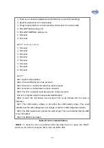
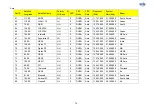
0x01: System has restarted
0x02: Unknown RS232 error has occurred
0x03: Unknown or invalid command has been received
0x04: Unknown or invalid data has been received.
0x05: The 'TS:' command must be sent prior to the command.
This is for programming the transponder/satellite data.
0x06: A tuner I2C bus failure has occurred. This could indicate that the tuner is
defective.
0x07: The LNB polarity voltage is not within the LNB polarity range. This could
indicate that the LNB voltage does not change or that the LNB voltage has shorted.
0x08: The LNB signal level is below the valid range. This could indicate that the LNB
is not connected.
0x09: The E2Ram has failed
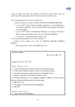
Table B-1 Error Code Definition
NOTE
: To clear the error by perforce after checking the error, press the ‘NEXT’
button on the ACU. If using the SCS, click the ‘ERR’ LED.
Содержание SUPERTRACK S4
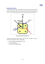
Страница 7: ...3 Figure 2 2 Best Location II Figure 2 3 Antenna Blockages ...
Страница 11: ...7 Figure 2 7 Tighten the nuts from below ...
Страница 13: ...9 Fixed Screws for Azimuth Figure 2 10 Fixed Screws for Azimuth ...
Страница 28: ...24 Figure 3 3 Antenna Control Unit Back Panel ...
Страница 44: ...40 1 Select the COM port 2 Select the Baudrate 3 Click the DISCONNECT Figure 4 2 Connection S4 with PC ...
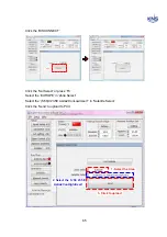
Страница 45: ...41 Connection Staus Antenna Current State Figure 4 3 Connection Status S4 with PC ...
Страница 48: ...44 Figure 4 6 Satellite List Update Step 2 ...
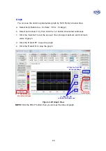
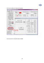
Страница 56: ...52 C N You can see the graph of C N on Antenna State Graph of C N Figure 4 13 C N Graph ...
Страница 71: ...67 Click the SAVE to save to PCU Click to Save ...
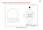
Страница 81: ...77 Appendix E Radome and Antenna Mounting Holes Layout Figure E 1 S4 Plastic Radome Layout ...