


70
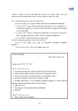
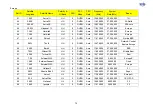
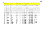
Table C-1 shows the error code definition, but this is a binary code. Thus, you
must convert the hexadecimal code to a binary code to confirm the error.
EX 1) Hexadecimal error code: ‘0X 18 08 00 00’
Convert to binary error code: 0X 00011000 00001000 00000000 00000000
1
5
error of FF
(1)
means that the satellite information is not acceptable (i.e.
the satellite longitude or current antenna latitude and longitude information
is not acceptable).
1
4
error of FF
(1)
refers to indicate that GPS fails in receiving in time (when
GPS normally receives the signal, the error message disappears)
1
4
error of FF
(2)
means that there is no gyro input.
EX 2) The hexadecimal error code: ‘0X 20 00 00 07’
Convert to the binary error code: 0X 00100000 00000000 00000000
00000111
Error refers to the 7
th
error of the DBS tuner error.
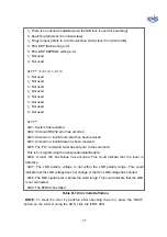
Error Code Define
PCU
Version:
after
1.94
Syntax: 0x: FF
(1)
FF
(2)
FF
(3)
FF
(4)
0x FF
(1)
=1
8
1
7
1
6
1
5
1
4
1
3
1
2
1
1
1
1
: Level motor driving error (clear if it returns to normal state in time)
1
2
: Cross motor driving error (clear if it returns to normal state in time)
1
3
: Yaw motor driving error (clear if it returns to normal state in time)
1
4
: GPS non valid error in time (clear if it returns to valid)
1
5
: Satellite information is not acceptable (satellite longitude or current antenna
latitude, longitude information)(clear if in normal state)
1
6
: DBS tuner error
1
7
: The stopper is not recognized during initialization
1
8
: Not used
0x FF
(2)
=1
8
1
7
1
6
1
5
1
4
1
3
1
2
1
1
1
1
: Home Index during initialization
Содержание SUPERTRACK S4
Страница 7: ...3 Figure 2 2 Best Location II Figure 2 3 Antenna Blockages ...
Страница 11: ...7 Figure 2 7 Tighten the nuts from below ...
Страница 13: ...9 Fixed Screws for Azimuth Figure 2 10 Fixed Screws for Azimuth ...
Страница 28: ...24 Figure 3 3 Antenna Control Unit Back Panel ...
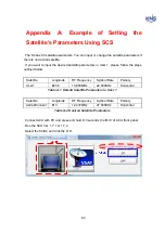
Страница 44: ...40 1 Select the COM port 2 Select the Baudrate 3 Click the DISCONNECT Figure 4 2 Connection S4 with PC ...
Страница 45: ...41 Connection Staus Antenna Current State Figure 4 3 Connection Status S4 with PC ...
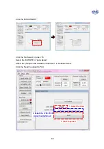
Страница 48: ...44 Figure 4 6 Satellite List Update Step 2 ...
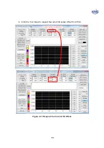
Страница 56: ...52 C N You can see the graph of C N on Antenna State Graph of C N Figure 4 13 C N Graph ...
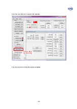
Страница 71: ...67 Click the SAVE to save to PCU Click to Save ...
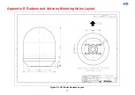
Страница 81: ...77 Appendix E Radome and Antenna Mounting Holes Layout Figure E 1 S4 Plastic Radome Layout ...