


46
SAT ID means satellite index like below.
ID 1~13: North America
ID 21~26: South America
ID 41~60: Europe
ID 61~74: Asia
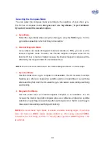
Search Ref means S4’s searching reference that used reference during the search
the satellite.
AGC THD: Search higher AGC level than preset AGC level in PCU.
C/N THD: Search higher C/N level than preset C/N level in PCU.
CLock: Search the target DVB Carrier lock.(Default)
Track Ref means S4’s tracking reference that used reference during the track the
satellite.
AGC: Track the highest AGC level.(Astra2Connect default).
C/N: Track the highest C/N level.(IPcopter default).
RSSD(Receive Signal Detector): Track the highest RSSD value(Not function).
RX Polarity means RX polarity of satellite.
Horizontal/Vertical
THRD Level means threshold level if searching reference is AGC THD or C/N THD.
Polarity means voltage and tone of LNB. S4’s default is ‘HH’
Linear LNB(Horizontal/Vertical, High/Low)
HH(18V, 22KHz)
HL(18V, 0KHz)
VH(13V,
22KHz)
VL(13V, 0KHz)
Circular LNB(Left Handed/Right Handed, High/Low)
LH(18V, 22KHz)
LL(18V, 0KHz)
RH(13V,
22KHz)
RL(13V, 0KHz)
Содержание SUPERTRACK S4
Страница 7: ...3 Figure 2 2 Best Location II Figure 2 3 Antenna Blockages ...
Страница 11: ...7 Figure 2 7 Tighten the nuts from below ...
Страница 13: ...9 Fixed Screws for Azimuth Figure 2 10 Fixed Screws for Azimuth ...
Страница 28: ...24 Figure 3 3 Antenna Control Unit Back Panel ...
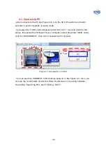
Страница 44: ...40 1 Select the COM port 2 Select the Baudrate 3 Click the DISCONNECT Figure 4 2 Connection S4 with PC ...
Страница 45: ...41 Connection Staus Antenna Current State Figure 4 3 Connection Status S4 with PC ...
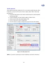
Страница 48: ...44 Figure 4 6 Satellite List Update Step 2 ...
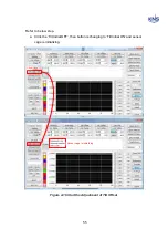
Страница 56: ...52 C N You can see the graph of C N on Antenna State Graph of C N Figure 4 13 C N Graph ...
Страница 71: ...67 Click the SAVE to save to PCU Click to Save ...
Страница 81: ...77 Appendix E Radome and Antenna Mounting Holes Layout Figure E 1 S4 Plastic Radome Layout ...