


32
a. Auto Mode
In the Auto mode, the ACU displays the skew angle calculated by the PCU. The
S4’s default skew mode is auto. The S4 automatically changes the skew angle
when the satellite is changed.
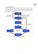
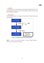
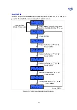
b. Manual Mode
The Installer or Operator can change the skew angle to the desired skew angle,
as shown below.
Figure 3-13 Setting the Skew Angle in Manual Mode
NOTE
: ‘C:’ refers to the current skew angle. ‘A:’ refers to signal strength. ‘S:’
refers to the user setting the skew angle.
Содержание SUPERTRACK S4
Страница 7: ...3 Figure 2 2 Best Location II Figure 2 3 Antenna Blockages ...
Страница 11: ...7 Figure 2 7 Tighten the nuts from below ...
Страница 13: ...9 Fixed Screws for Azimuth Figure 2 10 Fixed Screws for Azimuth ...
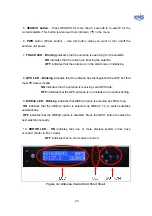
Страница 28: ...24 Figure 3 3 Antenna Control Unit Back Panel ...
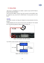
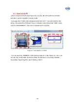
Страница 44: ...40 1 Select the COM port 2 Select the Baudrate 3 Click the DISCONNECT Figure 4 2 Connection S4 with PC ...
Страница 45: ...41 Connection Staus Antenna Current State Figure 4 3 Connection Status S4 with PC ...
Страница 48: ...44 Figure 4 6 Satellite List Update Step 2 ...
Страница 56: ...52 C N You can see the graph of C N on Antenna State Graph of C N Figure 4 13 C N Graph ...
Страница 71: ...67 Click the SAVE to save to PCU Click to Save ...
Страница 81: ...77 Appendix E Radome and Antenna Mounting Holes Layout Figure E 1 S4 Plastic Radome Layout ...