
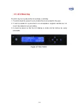


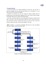


23
5.
SEARCH button
– Press SEARCH for more than 3 seconds to re-search for the
current satellite. This button is also used to scroll down (
▼
) in the menu.
6.
PWR
button (Power button) – Use this button when you want to turn on/off the
antenna unit power.
7.
TRACK LED
–
Blinking
indicates that the antenna is searching for the satellite.
ON
indicates that the antenna is tracking the satellite.
OFF
indicates that the antenna is in the stall mode or initializing.
8.
GPS LED
–
Blinking
indicates that the antenna has distinguished the GSP but that
the GPS data is invalid.
ON
indicates that the antenna is receiving valid GPS data.
OFF
indicates that the GPS antenna is not installed or is malfunctioning.
9.
DiSEqC LED
–
Blinking
indicates that DiSEqC option is selected as 22KHz tone.
ON
indicates that the DiSEqC option is selected as DiSEqC 1.2 to switch satellites
automatically.
OFF
indicates that the DiSEqC option is disabled. Press the NEXT button to select the
next satellite manually.
10
. ERROR LED
–
ON
indicates that one or more discrete system errors have
occurred. (Refer to Error Code)
OFF
indicates that no errors have occurred.
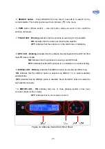
Figure 3-2 Antenna Control Unit Front Panel
Содержание SUPERTRACK S4
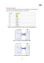
Страница 7: ...3 Figure 2 2 Best Location II Figure 2 3 Antenna Blockages ...
Страница 11: ...7 Figure 2 7 Tighten the nuts from below ...
Страница 13: ...9 Fixed Screws for Azimuth Figure 2 10 Fixed Screws for Azimuth ...
Страница 28: ...24 Figure 3 3 Antenna Control Unit Back Panel ...
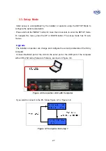
Страница 44: ...40 1 Select the COM port 2 Select the Baudrate 3 Click the DISCONNECT Figure 4 2 Connection S4 with PC ...
Страница 45: ...41 Connection Staus Antenna Current State Figure 4 3 Connection Status S4 with PC ...
Страница 48: ...44 Figure 4 6 Satellite List Update Step 2 ...
Страница 56: ...52 C N You can see the graph of C N on Antenna State Graph of C N Figure 4 13 C N Graph ...
Страница 71: ...67 Click the SAVE to save to PCU Click to Save ...
Страница 81: ...77 Appendix E Radome and Antenna Mounting Holes Layout Figure E 1 S4 Plastic Radome Layout ...