


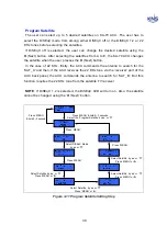

17
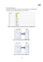
Connecting satellite TV receivers with European LNB (Use of the all
polarity of satellite)
In European systems that come with a Quattro LNB (optional Quad LNB), all four RF
outputs from the SuperTrack S4 antenna should be connected to the multi-switch.
Connect each of the satellite TV receiver’s inputs to the output connectors on the multi-
switch. Connect the multi-switch unit in accordance with the manufacturer’s instructions.
Figure 2-18 shows an example of a European multi-switch (4 inputs and 4 outputs)
configuration.
RF1: Low Band Vertical
RF2: Low Band Horizontal
RF3: High Band Vertical
RF4: High Band Horizontal
Figure 2-18 Four Satellites TV Receivers Installation with European LNB
If you want use more satellite TV receivers than four, you can choose 8 outputs
or 16 outputs.
Содержание SUPERTRACK S4
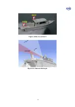
Страница 7: ...3 Figure 2 2 Best Location II Figure 2 3 Antenna Blockages ...
Страница 11: ...7 Figure 2 7 Tighten the nuts from below ...
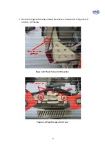
Страница 13: ...9 Fixed Screws for Azimuth Figure 2 10 Fixed Screws for Azimuth ...
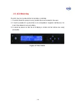
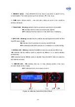
Страница 28: ...24 Figure 3 3 Antenna Control Unit Back Panel ...
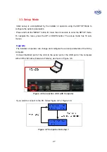
Страница 44: ...40 1 Select the COM port 2 Select the Baudrate 3 Click the DISCONNECT Figure 4 2 Connection S4 with PC ...
Страница 45: ...41 Connection Staus Antenna Current State Figure 4 3 Connection Status S4 with PC ...
Страница 48: ...44 Figure 4 6 Satellite List Update Step 2 ...
Страница 56: ...52 C N You can see the graph of C N on Antenna State Graph of C N Figure 4 13 C N Graph ...
Страница 71: ...67 Click the SAVE to save to PCU Click to Save ...
Страница 81: ...77 Appendix E Radome and Antenna Mounting Holes Layout Figure E 1 S4 Plastic Radome Layout ...