% 1
! !
$
(-
)
?
7
%0
1
7
?
<#
<
!
&
Min
Sheave
Dia (in)
Belt
Type
Max
#
of
Belts
Avg.
Deflected
Force
(lbs)
Min
Sheave
Dia (in)
Belt
Type
Max
#
of
Belts
Avg.
Deflected
Force
(lbs)
Min
Sheave
Dia (in)
Belt
Type
Max
#
of
Belts
Avg.
Deflected
Force
(lbs)
0.75
2.2
3VX
1
3.4
2.2
3VX
1
2.2
2.2
3VX
1
1.3
1
2.4
3VX
1
4.0
2.2
3VX
1
3.1
2.2
3VX
1
1.6
1.5
2.4
3VX
2
3.1
2.4
3VX
2
2.1
2.2
3VX
1
2.5
2
2.4
3VX
3
2.8
2.4
3VX
2
2.9
2.4
3VX
1
2.7
3
3.0
3VX
2
3.3
2.4
3VX
3
2.9
2.4
3VX
2
2.3
5
3.0
3VX
3
4.0
3.0
3VX
3
3.7
2.4
3VX
3
2.5
7.5
3.8
3VX
4
4.7
3.0
3VX
4
4.1
3.0
3VX
2
4.2
10
4.4
3VX
4
5.4
3.8
3VX
4
4.3
3.0
3VX
3
3.8
15
4.4
3VX
5
5.4
4.4
3VX
4
5.4
3.8
3VX
3
4.4
20
5.2
3VX
6
6.0
4.4
3VX
6
4.8
4.4
3VX
3
5.0
25
6.0
3VX
7
5.6
4.4
3VX
7
5.2
4.4
3VX
4
4.7
30
6.8
3VX
7
5.9
5.2
3VX
7
5.3
40
6.8
5VX
4
11.6
6.0
3VX
7
6.0
50
8.2
5VX
4
14.6
6.8
3VX
8
5.9
60
8.2
5VX
5
14.1
7.4
5VX
4
13.3
75
10.0
5VX
5
14.5
8.6
5VX
4
14.3
100
10.0
5VX
6
16.0
8.6
5VX
6
13
125
12.0
5V
7
14.1
10.5
5V
6
13.1
150
13.2
5V
7
15.4
10.5
5V
7
13.4
200
15.0
5V
8
16.0
13.2
5V
8
13.1
250
15.0
8V
6
27.6
14.0
5V
9
13.8
300
16.0
8V
7
27.1
14.0
5V
9 =
11 /
A
23.4
350
16.5
8V
7
30.3
14.5
5V/
=
12 /
A
26.0
400
17.5
8V
8
29.1
15.0
5V/
=
13 /
25.7
450
18
8V
8
31.6
16.0
5V/
=
14 /
K
25.2
500
18.5
8V
9
30.7
16.5
5V/
=
15 /
K
26.9
600
17.5
8V
11
26.3
700
19.0
8V
12
27.3
800
20.0
8V
13
28.2
+-
7
4
!
6
-
# &;
*
1.
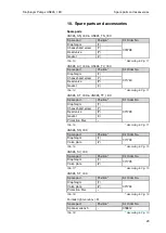
Horsepower is the nameplate motor horsepower, and RPM is the motor (driver) speed.
2.
Minimum sheave diameters are from NEMA standards where applicable.
3.
)
1
)
-
,
4.
Selections are based on a 1.4 service factor, 5 to 1 speed ratio and various Power Transmission Manufacturers’ catalogs.
5.
These selections are for Narrow V belt sections only. Consult manufacturer for details on conventional V belt sections (A, B, C, D and E), or other
belt types.
6.
“Average Deflected Force is per section 3.3.4.4 of this document and is the force required to deflect the center of a belt 1/64 of the belt span
distance. Tolerance on this force is ±1 lbf for forces
≤
10 lbs, and ±2 lbs for forces >10 lbs as measured utilizing a belt tension gage.
7.
When more than one belt is required the belts must be a matched set (matched for length).
8.
If possible, the lower side of the belt should be the driving side to increase the length of wrap on the sheave).
9.
For belted loads do not exceed 125% of 60 Hz operating RPM.
_________________________________________________________________________________________________________________________
!,!,
= ? =
1
:
0 ? )
; $ %
*
5 $
6*
= ?
+ - $
%-
;
UL Recognition, UL Listing, or CSA certification does not apply to
motors that are equipped with a manual or automatic reset thermal
protector when the motor is operated on VFD power.
5 $
6*
; +
*
Power factor correction capacitors should never be installed
between the drive and the motor.
/%
* = ? 9
(
*
It is the responsibility of the startup personnel during set up of the
VFD / motor system to properly tune the drive to the motor for the
specific application per the VFD user manual. The correct voltage
boost and volts per hertz settings are application dependent and
unique to each motor design. Failure to connect over temperature
devices (when provided) will void the warranty.
!,!, ,<
)
1
0*
Belted loads: Do not exceed 125% of 60 Hz operating RPM.
% 1
! @
B
(
(
$;
?
'
9 M
N
( 3
# ;
@
;
56 180
[80 110]
7200
5400
210 250 [130 160]
5400
4200
280
[180]
5400
3600
320
[200]
4500
3600
360
[225]
4500
2700
400 440 [250 280]
3600
2700
>440
[>280]
3600
1800
= Fan cooled motors (Totally Enclosed & Hazardous
Locations Motors) are limited to a maximum safe
continuous speed of 4000 RPM
- 4-
-
0 0
!,!, ,#
1
'
4 - *
For optimum insulation life,
limit VFD to motor cable lengths of general purpose motors


