Diaphragm pump N630 EX
Servicing
Translation of Original Operation and Installation Instruction, english, KNF 320945 04/21
41
Tool and material
Quan-
tity
Tool/material
1
TORX ® T30 screwdriver with torque indicator
1
Size 5 Allen key with torque indicator
1
Screwdriver blade width 5.5 mm
1
Felt-tip pen
1
19 mm open-end wrench (only for two-headed pumps)
1
PZ2 Phillips-head screwdriver (for fan cover)
Tab.21 *According to accessories list, Chapter 11.2 Accessories
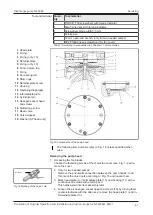
1
Head plate
2
O-ring
3
O-ring (only .13)
4
Retainer plate
5
O-ring (only .13)
6
Conrod plate, top
7
O-ring
8
Connecting rod
9
Shim rings
10
Retainer plate screw
11
Housing
12
Operating diaphragm
13
Intermediate plate
14
Cylindrical pin
15
Hexagon socket head
cap screws
16
Slotted cap screw
17
Reed valve
18
Valve stopper
19
Washer (ST head only)
Fig.18 Components of the pump head
The following item numbers refer to Fig. 18 unless specified other-
wise.
Removing the pump head
1. Accessing the fan blades:
Loosen the fastening screws of the motor fan cover (see Fig. 1) and re-
move the cover.
Union nut
Marking
Fig.19 Marking of the union nuts
2. Only for two-headed pumps:
Remove the pneumatic connection between the pump heads; to do
this, mark the union nuts according to Fig. 19 and loosen them.
3. Mark head plate (1), intermediate plate (13) and housing (11) with a
continuous line made with a felt-tip pen.
This helps avoid incorrect assembly later.
4. Loosen the six hexagon socket head cap screws (15) by turning them
counterclockwise with the Allen key; remove the head plate (1) and in-
termediate plate (13).
Содержание N630 EX
Страница 53: ......
Страница 54: ......
Страница 55: ......
Страница 56: ......
Страница 144: ...KNF worldwide You can find our local KNF partners at www knf com...


