ROTEX
®
Operating/Assembly instructions
KTR-N
Sheet:
Edition:
40210 EN
12 of 27
23
Please observe protection
note ISO 16016.
Drawn:
2019-07-02 Pz/Wb
Replacing:
KTR-N dated 2017-09-06
Verified:
2019-07-23 Pz
Replaced by:
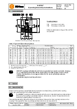
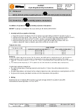
Table 9: Recommended fit pairs acc. to DIN 748-1
Bore [mm]
Shaft tolerance
Bore tolerance
above
up to
50
k6
H7
(KTR standard)
50
m6
If a feather keyway is intended to be used in the hub, it should correspond to the tolerance ISO JS9 (KTR
standard) with standard operating conditions or ISO P9 with complicated operating conditions (frequently
alternating torsional direction, shock loads, etc.). The keyway should preferably be located between the cams.
With axial fastening via setscrew the tapped hole should be positioned on the keyway except for Al-D which
should be positioned opposite the keyway.
The transmittable torque of the shaft-hub-connection must be reviewed by the customer and is subject to his
responsibility.
We recommend to inspect bores, shaft, keyway and feather key for dimensional accuracy
before assembly.
Heating the hubs lightly (approx. 80 °C) allows for an easier mounting on the shaft.
Please pay attention to the ignition risk in potentially explosive atmospheres!
STOP
Touching the heated hubs causes burns.
Please wear safety gloves.
!
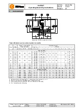
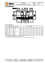
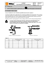
With the assembly make sure that the distance dimension E (see table 1 to 7) is observed to
allow for axial clearance of the spider when in operation.
Disregarding this advice may cause damage to the coupling.
If used in potentially explosive atmospheres the setscrews to fasten the hubs as well as all
screw connections must be secured against working loose additionally, e. g. conglutinating
with Loctite (average strength).
•
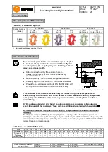
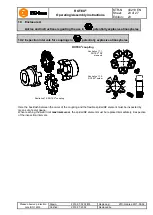
Mount the hubs on the shaft of driving and driven side (see illustration 10).
•
Insert the spider or DZ elements into the cam section of the hub on the driving or driven side.
•
Shift the power packs in axial direction until the distance dimension E is achieved (see illustration 11).
•
If the power packs are already firmly assembled, shifting the hubs axially on the shafts allows for setting the
distance dimension E.
•
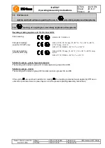
Fasten the hubs by tightening the setscrews DIN EN ISO 4029 with a cup point (tightening torques see
table 8).
If the shaft diameters with inserted feather key are smaller than dimension d
H
(see table 1 to
7) of the spider, one or two shaft ends may protude into the spider.
4
Assembly
4.2 Advice for finish bore
4.3 Assembly of the hubs
Содержание N630 EX
Страница 53: ......
Страница 54: ......
Страница 55: ......
Страница 56: ......
Страница 144: ...KNF worldwide You can find our local KNF partners at www knf com...


