


124
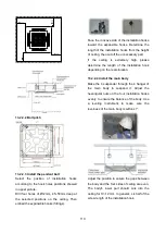
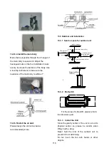
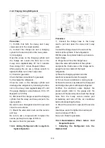
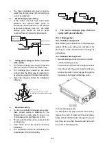
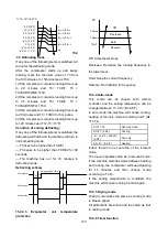
2.2 Power on and let the air conditioner
operate for cooling. Check operation status
of drainage pump, and then connect the
plug of water level switch, check the
operation sound of water pump and
observe whether the water can discharge
through the transparent hard pipe at
drainage outlet. (In light of the length of
drainage pipe, water shall be discharged
about 1 minute delayed)
2.3 Stop the operation of air conditioner, power
off the power supply and put the cover of
water test hole back to the original place.
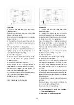
a. After stopped the air conditioner 3 minutes,
check whether there is anything abnormal.
If drainage pipes have not been distributed
properly, over back-flow water shall cause
the flashing of alarm indicator at
remote-controlled receiving board and
even water shall run over the water
collector.
b. Continuously infusing water until water
level alarmed, check whether the drainage
pump could discharge water at once. If
water level does not decline under warning
water level 3 minutes later, it shall cause
shutdown of unit. When this situation
happens, the normal startup only can be
recovered by turning down power supply
and eliminating accumulated water.
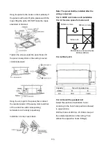
Note:
Drain plug at the main water-containing
plate is used for eliminating accumulated water
in water-containing plate when maintaining air
conditioner fault. During normal operation, the
plug shall be filled in to prevent leakage.
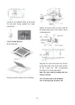
13.5.4 Insulation work of drainage pipe
Refer the introduction to the insulation
engineering parts.
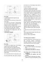
13.6 Vacuum Drying and Leakage Checking
13.6.1 Purpose of vacuum drying
Eliminating moisture in system to prevent
the phenomena of ice-blockage and copper
oxidation.
Ice-blockage shall cause abnormal
operation of system, while copper oxide
shall damage compressor.
Eliminating the non-condensable gas (air)
in system to prevent the components
oxidizing, pressure fluctuation and bad heat
exchange during the operation of system.
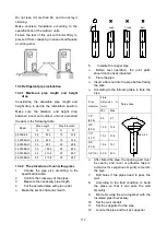
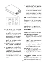
13.6.2 Selection of vacuum pump
The ultimate vacuum degree of vacuum
pump shall be -756mmHg or above.
Precision of vacuum pump shall reach
0.02mmHg or above.
13.6.3 Operation procedure for vacuum
drying
Due to different construction environment, two
kinds of vacuum drying ways could be chosen,
Содержание KDIP012-H2
Страница 8: ...5 2 2 Part names of Indoor Outdoor units Cassette Units ...
Страница 9: ...6 KDIR Duct Units ...
Страница 10: ...7 KDIP Duct Units ...
Страница 11: ...9 Ceiling floor Units ...
Страница 12: ...10 HESP DUCT Units ...
Страница 19: ...19 2 3 4 7 Outside Water Pump for Optional When Ceiling Installation ...
Страница 31: ...33 KSIE024 H220 O KSIR036 H218 inch 37 2 16 1 31 9 40 6 26 5 15 9 ...
Страница 34: ...36 Ceiling floor Units ...
Страница 39: ...41 KTIR036 H2G1 KTIR048 H2G1 ...
Страница 40: ...43 KUIR18 H2 KUIR24 H2 ...
Страница 41: ...44 KFUF036 H2G1 KFUF048 H2G1 ...
Страница 42: ...45 KFUF060 H2G1 ...
Страница 43: ...46 KFUF036 H2G1 KFUF048 H2G1 ...
Страница 44: ...47 KDIP090 H2 KDIP012 H2 KDIP018 H2 KDIP24 H2 ...
Страница 69: ...74 6 2 Outdoor Unit KSIE018 H220 O KSIE024 H220 O ...
Страница 70: ...75 KSIE009 H221 O KSIE012 H220 O ...
Страница 71: ...77 KSIR036 H218 ...
Страница 77: ...83 KDIR09 H2 Code 0 Code 1 Code 2 Code 3 Code 4 ...
Страница 78: ...84 KDIR12 H2 Code 0 Code 1 Code 2 Code 3 Code 4 ...
Страница 79: ...85 KDIR18 H2 Code 0 Code 1 Code 2 Code 3 Code 4 ...
Страница 80: ...86 KDIR24 H2 Code 0 Code 1 Code 2 Code 3 Code 4 ...
Страница 96: ...104 12 Field Wiring 9K 24K 36K 48K 60K ...
Страница 97: ...105 ...
Страница 147: ...155 P U P V ...
Страница 148: ...156 P W P N ...
Страница 174: ...184 4 Remove the evaporator support board 5 Screw off the fixing screws to remove the evaporator 4 screws 1 screw ...
Страница 181: ...191 4 Remove the evaporator fixing clamps to disassemble the evaporator Fixing clamps 1 screw ...
Страница 188: ...221 5 Remove the four fixing screws of the fan motor then remove the motor 5 ...
Страница 201: ...234 6 Remove the grounding screw 7 Remove the Wires 1 2 3 or L1 L2 S Then remove the electronic control box 7 5 ...