


121
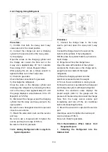
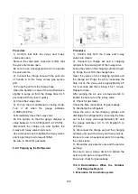
Procedure:
1).Confirm that both the 2-way and 3-way
valves are open.
2). Connect the vacuum pump to 3-way valve’s
service port.
3). Conduct an evacuation for approximately
one hour. Confirm that the compound meter
displays a value of -0.1Mpa(14.5Psi).
4). Close the valve (Low side) on the charge set,
turn off the vacuum pump. After 5 minutes,
confirm that the gauge needle is not moving.
5). Disconnect the charge hose from the
vacuum pump.
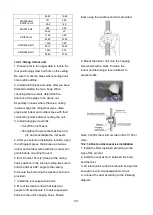
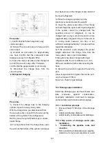
2. Refrigerant charging
Procedure:
1). Connect the charge hose to the charging
cylinder. Open the 2-way 3-way valve.
With the charge hose you disconnected from
the vacuum pump, connect it to the valve at the
bottom of the cylinder. If the refrigerant is
R410A, place the cylinder bottom-up to ensure
liquid charge.
2). To purge the air from the charge hose, open
the valve at the bottom of the cylinder and press
the check valve on the charge set (be careful of
the liquid refrigerant).
3) Place the charging cylinder onto the
electronic scale and record the weight.
4). Open the valves (Low side) on the charge
set and charge the system with liquid refrigerant
If the system cannot be charged with the
specified amount of refrigerant, or can be
charged with a only a small amount at a time
(approximately 150g each time),turn the unit on
in cooling mode; however, one time is not
sufficient, wait approximately 1 minute and then
repeat the procedure.
5).If the electronic scale displays the proper
weight, disconnect the charge hose from the
3-way valve’s service port immediately.
If the system has been charged with liquid
refrigerant while the air conditioner is on, turn
off the air conditioner before disconnecting the
hose.
6). Mount the valve stem caps and the service
port.
Use a torque wrench to tighten the service port
cap to a torque of 18N.m.
Be sure to check for gas leakage.
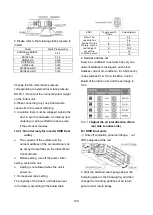
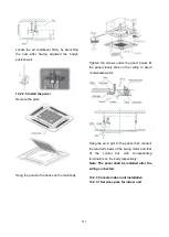
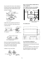
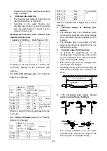
13.5 Drainage pipe installation
Install the drainage pipe as shown below and
take
measures
against
condensation.
Improperly installation could lead to leakage
and eventually wet furniture and belongings.
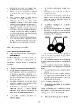
13.5.1 Installation principle
Ensure at least 1/100 slope of the drainage
pipe
Adopt suitable pipe diameter
Adopt nearby condensate water discharge
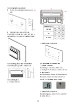
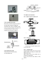
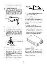
13.5.2 Key points of drainage water pipe
installation
1.
Considering the pipeline route and
elevation
Before installing condensate water pipeline,
determine its route and elevation to avoid
Содержание KDIP012-H2
Страница 8: ...5 2 2 Part names of Indoor Outdoor units Cassette Units ...
Страница 9: ...6 KDIR Duct Units ...
Страница 10: ...7 KDIP Duct Units ...
Страница 11: ...9 Ceiling floor Units ...
Страница 12: ...10 HESP DUCT Units ...
Страница 19: ...19 2 3 4 7 Outside Water Pump for Optional When Ceiling Installation ...
Страница 31: ...33 KSIE024 H220 O KSIR036 H218 inch 37 2 16 1 31 9 40 6 26 5 15 9 ...
Страница 34: ...36 Ceiling floor Units ...
Страница 39: ...41 KTIR036 H2G1 KTIR048 H2G1 ...
Страница 40: ...43 KUIR18 H2 KUIR24 H2 ...
Страница 41: ...44 KFUF036 H2G1 KFUF048 H2G1 ...
Страница 42: ...45 KFUF060 H2G1 ...
Страница 43: ...46 KFUF036 H2G1 KFUF048 H2G1 ...
Страница 44: ...47 KDIP090 H2 KDIP012 H2 KDIP018 H2 KDIP24 H2 ...
Страница 69: ...74 6 2 Outdoor Unit KSIE018 H220 O KSIE024 H220 O ...
Страница 70: ...75 KSIE009 H221 O KSIE012 H220 O ...
Страница 71: ...77 KSIR036 H218 ...
Страница 77: ...83 KDIR09 H2 Code 0 Code 1 Code 2 Code 3 Code 4 ...
Страница 78: ...84 KDIR12 H2 Code 0 Code 1 Code 2 Code 3 Code 4 ...
Страница 79: ...85 KDIR18 H2 Code 0 Code 1 Code 2 Code 3 Code 4 ...
Страница 80: ...86 KDIR24 H2 Code 0 Code 1 Code 2 Code 3 Code 4 ...
Страница 96: ...104 12 Field Wiring 9K 24K 36K 48K 60K ...
Страница 97: ...105 ...
Страница 147: ...155 P U P V ...
Страница 148: ...156 P W P N ...
Страница 174: ...184 4 Remove the evaporator support board 5 Screw off the fixing screws to remove the evaporator 4 screws 1 screw ...
Страница 181: ...191 4 Remove the evaporator fixing clamps to disassemble the evaporator Fixing clamps 1 screw ...
Страница 188: ...221 5 Remove the four fixing screws of the fan motor then remove the motor 5 ...
Страница 201: ...234 6 Remove the grounding screw 7 Remove the Wires 1 2 3 or L1 L2 S Then remove the electronic control box 7 5 ...