


117
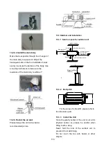
Do not lean it more than 45, and do not lay it
sidelong.
Make concrete foundation according to the
specifications of the outdoor units.
Fasten the feet of this unit with bolts firmly to
prevent it from collapsing in case of earthquake
or strong wind.
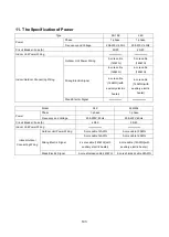
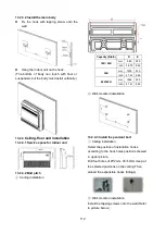
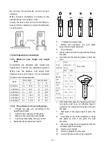
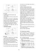
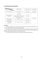
13.4 Refrigerant pipe installation
13.4.1 Maximum pipe length and height
drop
Considering the allowable pipe length and
height drop to decide the installation position.
Make sure the distance and height drop
between indoor and outdoor unit not exceeded
the date in the following table.
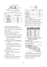
Model
Max. Length
Max. Elevation
m
Ft.
m
Ft.
9,000Btu/h
25
82.2
10
32.9
12,000Btu/h
25
82.2
10
32.9
18,000Btu/h
30
98.7
20
65.8
24,000Btu/h
50
164.5
25
82.2
36,000Btu/h
65
213.8
30
98.7
48,000Btu/h
65
213.8
30
98.7
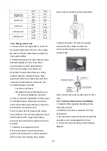
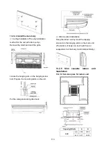
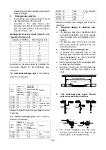
13.4.2 The procedure of connecting pipes
1.
Choose the pipe size according to the
specification table.
2.
Confirm the cross way of the pipes.
3.
Measure the necessary pipe length.
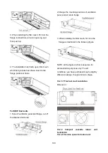
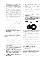
4.
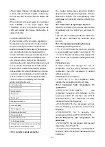
Cut the selected pipe with pipe cutter
Make the section flat and smooth.
90
Lean
Crude
Burr
o
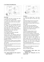
5.
Insulate the copper pipe
Before test operation, the joint parts
should not be heat insulated.
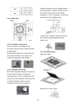
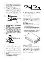
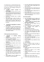
6.
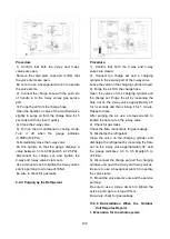
Flare the pipe
Insert a flare nut into the pipe before flaring
the pipe
According to the following table to flare the
pipe
Pipe
diameter
Flare
dimension A
(mm)
Flare shape
Min
Max
1/4"
(6.35)
8.3
8.7
R0.4~0.8
A
45°
90
°
4
-+
3/8"
(9.52)
12.0
12.4
1/2"
(12.7)
15.4
15.8
5/8"
(15.9)
18.6
19.1
3/4" (19) 22.9
23.3
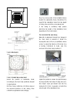
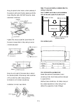
After flared the pipe, the opening part must
be seal by end cover or adhesive tape to
avoid duct or exogenous impurity come into
the pipe.
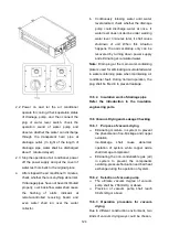
7.
Drill holes if the pipes need to pass the
wall.
8.
According to the field condition to bend
the pipes so that it can pass the wall
smoothly.
9.
Bind and wrap the wire together with the
insulated pipe if necessary.
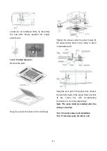
10. Set the wall conduit
11. Set the supporter for the pipe.
12. Locate the pipe and fix it by supporter
Содержание KDIP012-H2
Страница 8: ...5 2 2 Part names of Indoor Outdoor units Cassette Units ...
Страница 9: ...6 KDIR Duct Units ...
Страница 10: ...7 KDIP Duct Units ...
Страница 11: ...9 Ceiling floor Units ...
Страница 12: ...10 HESP DUCT Units ...
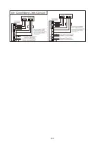
Страница 19: ...19 2 3 4 7 Outside Water Pump for Optional When Ceiling Installation ...
Страница 31: ...33 KSIE024 H220 O KSIR036 H218 inch 37 2 16 1 31 9 40 6 26 5 15 9 ...
Страница 34: ...36 Ceiling floor Units ...
Страница 39: ...41 KTIR036 H2G1 KTIR048 H2G1 ...
Страница 40: ...43 KUIR18 H2 KUIR24 H2 ...
Страница 41: ...44 KFUF036 H2G1 KFUF048 H2G1 ...
Страница 42: ...45 KFUF060 H2G1 ...
Страница 43: ...46 KFUF036 H2G1 KFUF048 H2G1 ...
Страница 44: ...47 KDIP090 H2 KDIP012 H2 KDIP018 H2 KDIP24 H2 ...
Страница 69: ...74 6 2 Outdoor Unit KSIE018 H220 O KSIE024 H220 O ...
Страница 70: ...75 KSIE009 H221 O KSIE012 H220 O ...
Страница 71: ...77 KSIR036 H218 ...
Страница 77: ...83 KDIR09 H2 Code 0 Code 1 Code 2 Code 3 Code 4 ...
Страница 78: ...84 KDIR12 H2 Code 0 Code 1 Code 2 Code 3 Code 4 ...
Страница 79: ...85 KDIR18 H2 Code 0 Code 1 Code 2 Code 3 Code 4 ...
Страница 80: ...86 KDIR24 H2 Code 0 Code 1 Code 2 Code 3 Code 4 ...
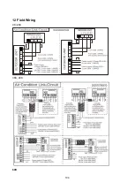
Страница 96: ...104 12 Field Wiring 9K 24K 36K 48K 60K ...
Страница 97: ...105 ...
Страница 147: ...155 P U P V ...
Страница 148: ...156 P W P N ...
Страница 174: ...184 4 Remove the evaporator support board 5 Screw off the fixing screws to remove the evaporator 4 screws 1 screw ...
Страница 181: ...191 4 Remove the evaporator fixing clamps to disassemble the evaporator Fixing clamps 1 screw ...
Страница 188: ...221 5 Remove the four fixing screws of the fan motor then remove the motor 5 ...
Страница 201: ...234 6 Remove the grounding screw 7 Remove the Wires 1 2 3 or L1 L2 S Then remove the electronic control box 7 5 ...