background image


65 

7.4 Using Segment Edit to Smooth Curved Sections 

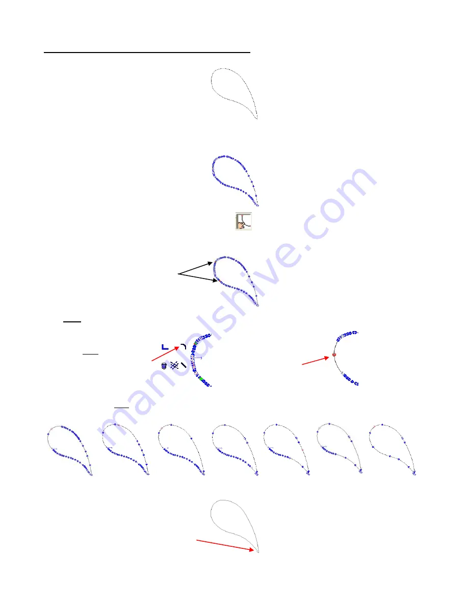
Segment Edit can be used to make uneven curves smoother and more natural. This is our example: 


(1) 

If necessary, use 

Ctrl-J

 to break the paths of the traced image. While there is a Segment Edit function in 

the Polygon Editing Mode, much better results are achieved in the Polyarc mode. Thus, convert the image 
by going to 

Arrange>Convert to>Polyarc

. Double click to bring up the nodes: 


(2) 

Click on the 

Segment Edit

 icon on the Smart Bar. 


(3) 

Click once at the beginning of the segment you wish to edit and then again at the end of the segment. The 
segment will turn red: 


(4) 

Right click anywhere and a popup window of icons, similar to the node edit menu, will appear. Select the 
top right icon, which is the 

Arc Segment

 option: 


(5) 

You can continue this process by again, clicking once along the path and then again further along the 
path, and then right to bring up the menu. Repeat around the path, as needed, to smooth out the curve 
and reduce excess nodes.  


(6) 

Click on 

Apply

 to close the Polyarc Editing window. Notice that everything looks fine, except for the very 

bottom part.  This will be addressed in the next step: 


(7) 

The other icons in the 

Segment Edit

 popup menu also allow straight lines, corners, and even guide lines 

to be created. 

Segment turns red 
between two points 
selected. 

Right click to bring 
up menu and select 
curve icon.      


The curve is now 
smoother and the 
nodes are reduced. 

Needs editing 

Содержание Groove E

Страница 1: ...e all recommended settings before operating You can only install and activate the software on TWO computers Thus carefully select which computers you wish to use and follow the instructions carefully...

Страница 2: ...K STUDIO SCREEN 19 3 2 TOOLS TOOLBAR WHERE THE GOOD STUFF RESIDES 20 3 3 MANAGING FILES 20 Opening a New Document Sign Blank Setup 20 Opening an Existing KNK File 21 Saving and Exporting 22 3 4 MANIPU...

Страница 3: ...NG DINGBAT IMAGES IN A TITLE 48 5 10 WELDING TEXT TO FRAMES 48 5 11 BADGES 49 5 12 STENCILING LETTERS 51 5 13 THE FONT DETECTIVE 52 6 TRACING 53 6 1 AUTO TRACING USING THE PREPARE TO VECTORIZE WIZARD...

Страница 4: ...AWING IN COLOR 83 9 5 USING THE ENGRAVING EMBOSSING DROP IN TOOL 85 9 6 USING THE PUNCH TOOL 85 9 7 USING INSTANT REPLAY AND THE STORAGE BIN 86 9 8 BLOCK NESTING 86 9 9 FILE CONVERSIONS 87 Converting...

Страница 5: ...r delivery then it will be the responsibility of the owner to ship the damaged KNK back to Accugraphic for repair Transporting When transporting the cutter move the pinch wheel levers into the upward...

Страница 6: ...lt On Front Table Pinch Wheel Total of 3 2 on Groove E Pinch Wheel Positioning Label Total of 4 5 on 24 Cutting Strip Grit Shaft beneath Pinch Wheels Total of 4 5 on 24 Power Port On Off Switch USB Po...

Страница 7: ...for a few seconds when cutter is first turned on Then the cutter will come to rest in the Online Mode Experiment with and buttons as shown 7 Offline Mode moves carriage to the left Online Mode increa...

Страница 8: ...or the Traverse Velocity Change the Baud Rate based on the connection you are using Increases Decreases Traverse Velocity Speed Increases Decreases Baud Rate USB 57600 Serial 9600 Step 5 In Online Mod...

Страница 9: ...the blade holder All of the non blade ends are inserted with the useful sharp end protruding through the bottom Blade Installation The blade must be carefully inserted into the blade holder Do this ov...

Страница 10: ...ny new owners this may seem like a difficult task but it only takes a little practice and then setting the blade length will seem quite easy to do It s also important to have the blade holder mounted...

Страница 11: ...tic scraper an old credit card will suffice to scrape off any random material pieces remaining on the mat after a cut For finer particles of paper or lint you can use a lint roller Tear off a sheet an...

Страница 12: ...nd put the bottom screws back in Once the screws are tightened turn the KNK back over where the cutter is facing up Insert 4 of the 8 screws that were packaged inside the box with the tables Be sure t...

Страница 13: ...r needed Note that if you activate on a second computer the license files will be different from those generated on your first computer so avoid mixing them up It s a good idea to back up these files...

Страница 14: ...Edit box and change the Baud rate to 9600 Also refer to Section 1 4 Step 4 where it shows how to change the Baud rate on the Keypad Panel as well Changes in both locations are necessary for the serial...

Страница 15: ...24 or whatever width matches your cutter s limit If working in metric enter the appropriate equivalents in mm Multiple Instance Go to Options Multiple Instance allows more than one file to be opened a...

Страница 16: ...pen holder and replace the top Make sure the pen will write by scribbling on scrap paper Then loosen the screw on the blade holder seat and insert the pen tool Make sure the pen nib is slightly above...

Страница 17: ...Not Available message i Verify that the COM Port assignment under Device Manager is the same as what has been assigned in KNK Studio Review steps in Section 2 1 Installation of the KNK and Software i...

Страница 18: ...are BEFORE removing from mat note which side is the X axis and which is the Y The Y side runs from left to right as you face the cutter 9 Use a ruler with at least 1 16 markings to measure the sides o...

Страница 19: ...e toolbars from the menu By resting your mouse over any of the toolbar icons a popup will appear indicating that icon s name function More information about the Tools toolbar is presented in Section 3...

Страница 20: ...with these hot keys can also help you become familiar with various functions in the software 3 2 Tools Toolbar where the good stuff resides The Tools toolbar contains the most common tools for image c...

Страница 21: ...that this has nothing to do with setting the origin on the cutter This simply sets the relative location of objects inside your Sign Blank Select the Orientation setting of Landscape or Portrait for...

Страница 22: ...ouse If you click on your middle mouse button it will toggle on the Hand cursor which then allows you to move your image around on the screen also referred to as panning There is also a Zoom Tools ico...

Страница 23: ...utton on the center square A new cursor with double headed arrows will appear You can now move the image to another location on the screen If you hold down the Ctrl key while moving the object it will...

Страница 24: ...t from changing locations in the Sign Blank be sure to turn the middle box red in the little diagram of 9 boxes up on the Smart Bar Stretching is similar to resizing but with a different algorithm tha...

Страница 25: ...art Bar allow customization of how the Line Style appears Arranging Under Layout Arrange and Distribute you have several options for aligning objects 1 Based on the last object created 2 Based on the...

Страница 26: ...ck on a drop down menu to select the layout you wish to use In general if you plan to fill the entire page you would select the default grid 3 Below this setting you can choose either Object to Object...

Страница 27: ...pear in the cutting window and then select which colors to cut and which ones to ignore Refer to Section 4 4 Cutting by Color o Banner Fill Banner Fill is used with the engraving tip to provide filled...

Страница 28: ...o Low will speed up the cut but may result in a poorer drawing resolution Setting the smoothing to High will slow down the cut but the cutting will be more accurate Move allows for an automatic offset...

Страница 29: ...ials raise the blade holder slightly so that the tip is a tiny bit higher Refer to Section 9 1 Cutting Chipboard for more details Speed With the cutter in Online mode press the top and bottom or butto...

Страница 30: ...u have your media on the mat and the mat inserted into the cutter Do you have the rollers positioned under the rectangle markers on the cutter Do you have the rollers protected from the adhesive on th...

Страница 31: ...ift the levers in the back Slide the mat into the cutter aligning it along the right side or left side of the machine The marked areas on the mat are based on the mat being aligned to the far right si...

Страница 32: ...ign Blank mode using the Select Mode icon refer to diagram below 18 Also if you are in Page Mode versus Sign Blank mode the overall size of your image is shown to the right of the location information...

Страница 33: ...e name changes are specific to the current file only which makes this feature all the more useful Method B Filter By Color 1 Select your images in the main document window and then click on the Cut To...

Страница 34: ...the blade holder to cut the image afterwards Of course you have the option to only select the color to be pounced while still in the main window However it is also possible to turn on pounce after en...

Страница 35: ...tal and Vertical In the Cut window when the Sort Dialog Box is opened one also has the option of checking a box which will then number the objects on the screen showing the cut order Object Start Poin...

Страница 36: ...mple above a value of 14 0 is entered for X and a vaule of 27 5 is entered for Y 8 After entering X and Y values click on Apply and OK 9 It is recommended that you perform a test Print and Cut to veri...

Страница 37: ...ve the paper forward or backwards by hand Use the left and right and buttons to move the alignment pin until it is directly over the red circle on the calibration sheet and will puncture the very cent...

Страница 38: ...the Shapes Tool icon on the Tools toolbar click on the Multi Registration Mark icon third from the right In the Smart Bar will be a menu choice of marks to use Pick the symbol 6 th from the left side...

Страница 39: ...are close to the outside margins you may need to check a Borderless Printing option as well Then close this window to return to the Print window 7 Check the box next to Preview Then click on the Prefe...

Страница 40: ...the front right corner of the material you are cutting 14 Return to Online mode by pressing the Online button 15 Use Ctrl A to select the image and registration marks Select the Cut Tool icon from th...

Страница 41: ...Align perfectly on your printout with the arrow keys and click on Set Position You have now set the positions of three registration marks The fourth is not needed 23 Click on OK The image will be cut...

Страница 42: ...e required 2 Print the image onto ordinary printer paper and set aside 3 Using the Klic N Kut cut the image from your cardstock paper or other material This is just like cutting an ordinary die cut 4...

Страница 43: ...original DOS 8 character restriction click on Convert and then locate the fontlist ini file contained in your c Klic N Kut Studio folder To uninstall fonts from KNK Studio 1 On the Tools toolbar click...

Страница 44: ...nd apply them to another 1 Select the title with the format you wish to copy right click and select Settings Check which format settings you wish to copy Click on OK 2 Right click again on this same t...

Страница 45: ...e size of your mat You can RIGHT click on the arrows to open a window for resetting the default increment for each click of the arrows 10 Further to the right click on the colored rectangular box and...

Страница 46: ...Note that outline and inline are a handy way to change the thickness of a font If you find you like the style of a font but the ligatures are too thin and the cut lettering tears easily when trying to...

Страница 47: ...Text Basics 2 Select both objects and go to Transform Fit Text to Path Pick any of the available options for a variety of looks 3 To specifically set the starting point of the text along a path click...

Страница 48: ...ion 5 4 Connected Letter Title with a Mat but do not weld yet Instead select the title and go to Arrange Text to Graphics Now the letters can be treated individually Marquis select the left side and d...

Страница 49: ...nd use the third tool XOR Weld to transform the two rectangles into a frame In Outline Mode you will not see a difference however in Fill Mode you will see that a frame has been created 11 Use Ctrl A...

Страница 50: ...Use Compression of Original Copy will open Check that box also This will compress longer names to fit into the boundaries of your original word 8 Check the box next to Replacement data file select wh...

Страница 51: ...ng a stencil and typing the name BABY then the interior parts indicated by the arrows would be lost and the resulting stencil would appear as in the figure on the right To avoid this a procedure calle...

Страница 52: ...tective is organizing fonts into groups that will then appear in the Font Selection window on the Text mode Smart Bar As an example let s say you want all of your ttf fonts to be assigned to a special...

Страница 53: ...the L shaped cursor appears you can left click once to paste the image into the Sign Blank in its original size Drag a corner to resize for viewing on the screen as desired 2 With the image selected...

Страница 54: ...ick on OK and then either double click your new image or select the first icon Accuscan under the Scan Tools menu on the Tools toolbar The following Smart Bar will appear at the top of your screen Bla...

Страница 55: ...s to the settings were made Tolerance reduced to 3 Corners reduced to 4 Small Shape Accuracy turned off and Overlay selected The new image was greatly improved and is ready to cut Note that you can us...

Страница 56: ...on OK Use the Accuscan method to autotrace In the first pass the default of Logo Long Lines and Curves was chosen The result shows that the image still ended up with random specks being traced To rem...

Страница 57: ...19 You will then see the Super Size window open as in the earlier examples and settings can be tweaked to achieve a better quality image In the following image the Contrast was increased and the Soft...

Страница 58: ...Accuscan process in Section 6 1 Check the box next to Centerline Trace Only and the box next to the bottom right yellow diagram Try the other settings shown below but make changes based on how your im...

Страница 59: ...t tracing you can use the Graphics Edit Tools to trace manually You may also wish to learn these tools to design images from scratch It s a very easy process and can be done quickly Further learning t...

Страница 60: ...tline doesn t show up yet because the tracing process is still underway but the nodes being planted in each corner do appear 7 Finish tracing the perimeter ending at the first node Note that because y...

Страница 61: ...the outside of the flower 4 In general you will need more nodes when tracing around tight curves and far fewer nodes when tracing along gentle curves As you practice this technique you will see that...

Страница 62: ...design Note that you can easily switch from one mode to the other without stopping the trace When you reach a point where you wish to switch right click and select the circle icon to switch to curve t...

Страница 63: ...y line Besides double clicking a line you can also use Edit Edit Path or Ctrl E to show the individual nodes A vector image can be either polyarc all nodes are curved nodes or polygon mixture of three...

Страница 64: ...old the Shift key and repeat in a different area to select more nodes at the same time 4 Press the U key on the keyboard and every other node will be selected in red Press the Delete key and those sel...

Страница 65: ...ht click anywhere and a popup window of icons similar to the node edit menu will appear Select the top right icon which is the Arc Segment option 5 You can continue this process by again clicking once...

Страница 66: ...rt Bar which can be used to erase portions of a path Indent the Delete icon the left trash can You can now click on any path between two nodes and it will be erased Indent the Delete Segment icon the...

Страница 67: ...he center box to move the lower portion of the star away from the upper Return to the original star Instead of selecting the first Ginsu knife icon select the second Close Path icon and repeat the pro...

Страница 68: ...tered Try 0 5 If the gaps fail to close try a higher value even 1 0 Close Graphics Arrange Close Graphics is similar to Connect Path except the two nodes to connect must be on the same contiguous path...

Страница 69: ...ath the hole turns white and will now appear Tag with fill turned off Tag with fill turned on Tag with fill turned on after Make Path is applied 7 9 Example of Editing a Vectorized Image Using the inf...

Страница 70: ...nife process to separate the leaf from the stem In this case the left mouse button was held down and a hand drawn curve was used to separate the stem from the leaf for a more natural look 9 At this po...

Страница 71: ...other locations with your mouse To delete a guideline from outside the Edit Guides window hold down the Shift key and right click on the guidelines To turn on labeling go to View Show Guide Labels Ev...

Страница 72: ...esign Modifying a Star From the Shapes Tools draw a Star in this example 6 points were selected and then drag one of the semicircle handles along one side of the star Then drag the other semicircle ha...

Страница 73: ...ection 5 10 Welding Text to Frames and Section 5 12 Stenciling Letters AND Weld Circle 15 point star Overlap shapes Use AND Weld Tools toolbar Result Crown Or Fern XOR Weld Two overlapping circles Use...

Страница 74: ...c This long handle will not be a part of your final arc it is only there to help control the shape The further away you drag this handle the more control you will have 3 Continue to hold down the left...

Страница 75: ...r corners as shown in third star Fillet Round Corner Unlike with the previous Round Corner which is applied to all exterior or interior corners Fillet Round Corner can be applied individually to any o...

Страница 76: ...nal cut images will look Render to Bitmap Occasionally you may have a reason to convert a vector image to a bitmap image For example you might want to design a Print and Cut tag and place lettering in...

Страница 77: ...up down to form arcs Use Transform Round Corner to create the final design 8 9 Decorative Border Go to Layout Decorative Border In the Smart Bar there are four choices for the exterior style With each...

Страница 78: ...ce Designs 1 Draw a square and make it 25 on both sides 2 Select the square and go to Layout Array Duplicate the settings shown here Then click on Close 3 Use Ctrl A to select all of the boxes and go...

Страница 79: ...ual tracing is performed using the Graphics Edit Tools on the Tools toolbar Select the middle tool called Free Edit You can now use the mouse to freely draw on the screen Unlike Node Edit mode in Free...

Страница 80: ...s in KNK Studio and the information on Page Control in Section 9 10 Features for Professionals There are five tools under the Measure Tools icon on the Tools toolbar Some are useful during the design...

Страница 81: ...clean cutting is obtained On the newer KNK s the test rings can be slipped over the bottom of the blade holder and used as spacers to lift the blade holder in the blade holder seat For future referenc...

Страница 82: ...t the Plotter tab Under Origin you will see the bottom left corner indented in the small diagram This actually represents the front right corner of the cutter as the software s default orientation is...

Страница 83: ...a sticky mat to prevent slippage during the cut Dedicate a mat to cutting only fabric or felt and apply a more permanent adhesive Also because of the fibrous nature of fabric and felt it is recommende...

Страница 84: ...iciently but may not give you the look you want Fill Overlap Adjust either the amount or the percentage These two values are linked and modifying one will alter the other Again refer to the settings i...

Страница 85: ...ol This allows for deeper impressions to be made on the material When you return to using the mat and knife it is fine to leave the felt strip in place It will not interfere with your cutting Recommen...

Страница 86: ...essure or Punch at a higher pressure to create the holes Also when positioning these tiny circles you may wish to use Transform Fit Object to Path 9 7 Using Instant Replay and the Storage Bin At any t...

Страница 87: ...to Trace 1 Install Screen Hunter King Kong Capture or any other free screen capturing program that allows you to marquis select a portion of your window for copying to the Windows clipboard In this ex...

Страница 88: ...Nodes to reduce the number to a reasonable amount for cutting Converting from KNK to GSD GSD is the format used by the Craft Robo Wishblade and Silhouette There are two methods for converting an imag...

Страница 89: ...se programs save the file as eps in KNK Studio When importing into WinPC Sign Funtime or Inspiration Studio select Convert to Vector when asked You can also use the ai file format in place of eps From...

Страница 90: ...l value say 0 00001 and then click on OK Then try the Arrange Break Path again 5 Also during this process you can try to individually click on border lines or random text labels to delete You may need...

Страница 91: ...start with a Sign Blank of a desired size and create four text objects with any text in the font and font size you wish to see Move these objects to any location inside or outside the Sign Blank area...

Страница 92: ...on your workspace and the KNK Studio toolbars and menu will be visible again To return to Excel marquis select the document and then double click on any of the nine bounding boxes Notepad Calculator...

Страница 93: ...do last action Edit Undo also 3rd icon from right on System toolbar Alt Backspace Undo last action Edit Undo also 3rd icon from right on System toolbar Ctrl Backspace Redo last action Ctrl R Repeat la...

Страница 94: ...Object E Align to last object centers horizontally Layout Align to Last Object L R Align to last object left right Layout Align to Last Object Align to Selected Alt 1 Arrange objects to left side Layo...

Страница 95: ...al contour R S T U V Remove selected node Snap to intersection Toggle start point Unselect half of the selected nodes Snap to nearest vertical grid line Miscellaneous F1 KNK Reference Guide Help Index...

Страница 96: ...ombined path of objects into individual paths for each object This is required in order to delete paths and edit nodes in a traced design Arrange Break Path Carrier Sheet Refer to Mat Center Nub When...

Страница 97: ...lso used to perform global color substitutions such as instantly replacing all shapes of a given color with another color View Show Palettes Show Job Palette Jog Use the Jog feature when an image is p...

Страница 98: ...cking especially if detailed objects are being cut Tools Toolbar Shapes Tools Proportional Scaling When the Proportional Scaling icon is locked the aspect ratio is held constant if the length or width...

Страница 99: ...urved line In node edit mode it appears as a small triangle Template A Template operation is used to convert a text object into a date time graphic or text input variable which is then saved with the...

Страница 100: ...ontact the file designer to find out which font was used and install the font if you have it B The file you are opening may have all text already converted to a graphic Again choose any replacement fo...

Страница 101: ...re from the air Blow dry your cardstock before cutting if the cardstock has been exposed to high humidity The KNK will cut two or three words perfectly but anything after that is a surface cut The bla...

Страница 102: ...he top When I try to move an object with my mouse it suddenly jumps up outside of the Sign Blank area A A built in function called Smart Move in some mouse brands can cause this Go to File Control Pan...

Страница 103: ...the nodes I cannot move them Check to make sure Snap to Grid isn t turned on Options Grid Snap to Grid I cannot weld together two images A The images must be the same color B The images must both hav...

Страница 104: ...f degrees that need to be corrected For example a setting of 5 degrees will correct lines that are off by that amount If the Degrees cannot be set high enough then the document should be scanned again...

Страница 105: ...artup 21 Display Sort Dialog 35 Display Units 20 Divide 77 Drag Knife 27 Duplicate 23 Duplicates 15 Edit Guides 71 Edit Path 63 Embossing 27 83 85 Embossing Engraving Tip 10 Enable Jogging 40 Enable P...

Страница 106: ...cting 22 Sequence 35 Sequence by List 35 Sequence by Vector 35 Serial Connection 13 Settings for Your Materials 29 Shadow 76 Sheet Layer Palette 25 80 Shop Palette 19 23 25 Show Fill 15 22 Show Filter...

Отзывы: