37
Calibrating the Alignment Pin (Groove E Model Only)
This calibration is necessary to make sure your print and cuts are accurate. It only needs to be done one time. It
is recommended that you take note of the final calibration numbers in case you ever need to reinstall the
software.
(1) It is necessary that metric be used in the calibration process. To temporarily switch KNK Studio to metric,
go to
Options>Toggle Units
.
(2) A calibration sheet has been included in your box. If it is missing, you can download this file from:
http://www.scrapbookdiecutter.com/downloads.htm
(3) Insert the alignment pin into the hole on the blade holder seat.
(4) Insert a blade into the blade holder and make sure enough blade protrudes to puncture the calibration
sheet. Insert the blade holder into the blade holder seat on the cutter.
(5) Do not place the calibration sheet on the mat; you will not be cutting. Instead, raise the pinch wheel levers
and insert the paper into the cutter, aligning it evenly along the right side of the machine.
(6) Press the
Online
button to go to offline mode. Because the pinch wheels have not been lowered you can
manually move the paper forward or backwards by hand. Use the left and right “+” and “
-
“ buttons to move
the alignment pin until it is directly over the red circle on the calibration sheet and will puncture the very
center of that circle. Again, make sure the calibration sheet is snug against the right side of the machine.
Gently push the blade holder down to puncture a hole in the calibration sheet. Then remove the sheet:
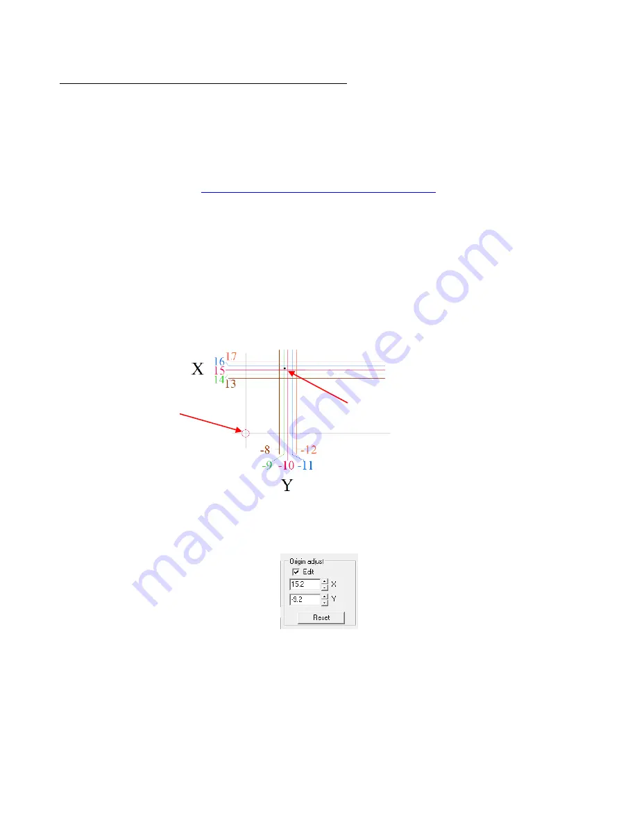
(7) The location of the puncture indicates the (X,Y) values to be entered into the
Origin Adjust
setting in the
software. Go to
Cut>Plotting
Defaults
and click on
Setup
. Select the
Plotter Options
tab. Check the
Edit
box. For the example above a value of 15.2 is entered for
X
and a vaule of -9.2 is entered for
Y
.
(8) After entering
X
and
Y
values, click on
Apply
and
OK
.
(9) It is recommended that you perform a test Print and Cut to verify that your calibration is accurate. You can
tweak the values if necessary based on the offset you receive in your test. For example, if you perform a
print and cut on an arrow which points from left to right on the screen and the printout, then note how the
calibration should be modified based on the following results:
Puncture is just above X = 15 and just to the
right of Y = -9. Thus the calibration values to
enter might be X: 15.2 and Y: -9.2.
Position alignment
pin at the center of
the red circle.


