4-10
CHAPTER 4 Maintenance and Troubleshooting
Series 5000 V2 Sonar System Operations and Maintenance Manual
P/N 11214512, Rev. 04
4.7.1 Checking the Multiplexer Board
The Multiplexer board is shown Figure 5-2 on page 5-3. When checking voltages,
unless otherwise noted, use TPGND1 as the ground reference. Reference
designations are printed on the board.
To check the Multiplexer board, do the following:
• Verify that 200 VDC is present on JP8 and that orange LED D40 is
illuminated.
• Verify that +5 VDC is present at L37 and that green LED D37 is
illuminated.
• Verify that -5 VDC is present at L30 and that green LED D38 is
illuminated.
• Verify that +3.3 VDC is present on the output side of L26 and that
green LED D39 is illuminated.
• Verify that +28 VDC is present at TP25. Use TPGND8 as the
ground reference.
• Verify that +2.5 VDC is present at TP9 and that green LED D9 is
illuminated. The +2.5 VDC is generated from the +3.3 VDC.
• Verify that +1.2 VDC is present at TP10 and that green LED D11
is illuminated. The +1.2 VDC is generated from the +3.3 VDC.
In addition, refer to Figure 4-14 for some applicable waveforms.
4.7.2 Checking the Transmitter Board
By probing on the Transmitter board you can check that the transmitters are
working. Probe each transmitter output connector (J5-1, 2; J6-1, 2) to view the two
transmitter outputs. These are floating differential output pairs, so the signal levels
at pin 1 and 2 may be unequal. But all four pins should show transmitter outputs
similar to that shown in Figure 4-14, and you should see a scope trace similar to
the one shown in the figure. You can select different pulse lengths on the System
5000 Control tab of the
Sonar Interface
dialog box. Note that pulse lengths of 2 ms
and greater are generated at a lower amplitude than shorter pulse lengths. The
altimeter transmitter can be checked at J7-1.
4.7.3 Checking the Receiver Boards
If your sonar image seems to be having problems on one side, this is an indication
that you may have a receiver problem. Try swapping the receiver boards and see if
the problem follows the board.
Содержание 5000 V2 Series
Страница 24: ......
Страница 48: ......
Страница 62: ......
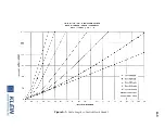
Страница 73: ...A 3 Figure A 1 Cable Length vs Towfish Depth Graph 1...
Страница 75: ...A 5 Figure A 3 Cable Length vs Towfish Depth Graph 3...
Страница 77: ...A 7 Figure A 5 Cable Length vs Towfish Depth Graph 5...
Страница 78: ......
Страница 82: ......
Страница 88: ......
Страница 92: ......
Страница 95: ...E 3...
Страница 97: ...E 5...
Страница 99: ...E 7...
Страница 101: ...E 9...
Страница 103: ...E 11...
Страница 105: ...E 13...
Страница 107: ...E 15...
Страница 109: ...E 17...
Страница 111: ...E 19...


