KS / KG / KGA 740 - LO
KLEIBER-Pyrometer
Operation Manual
Betriebsanleitung
Fast measurement, fast controlling, fast switching
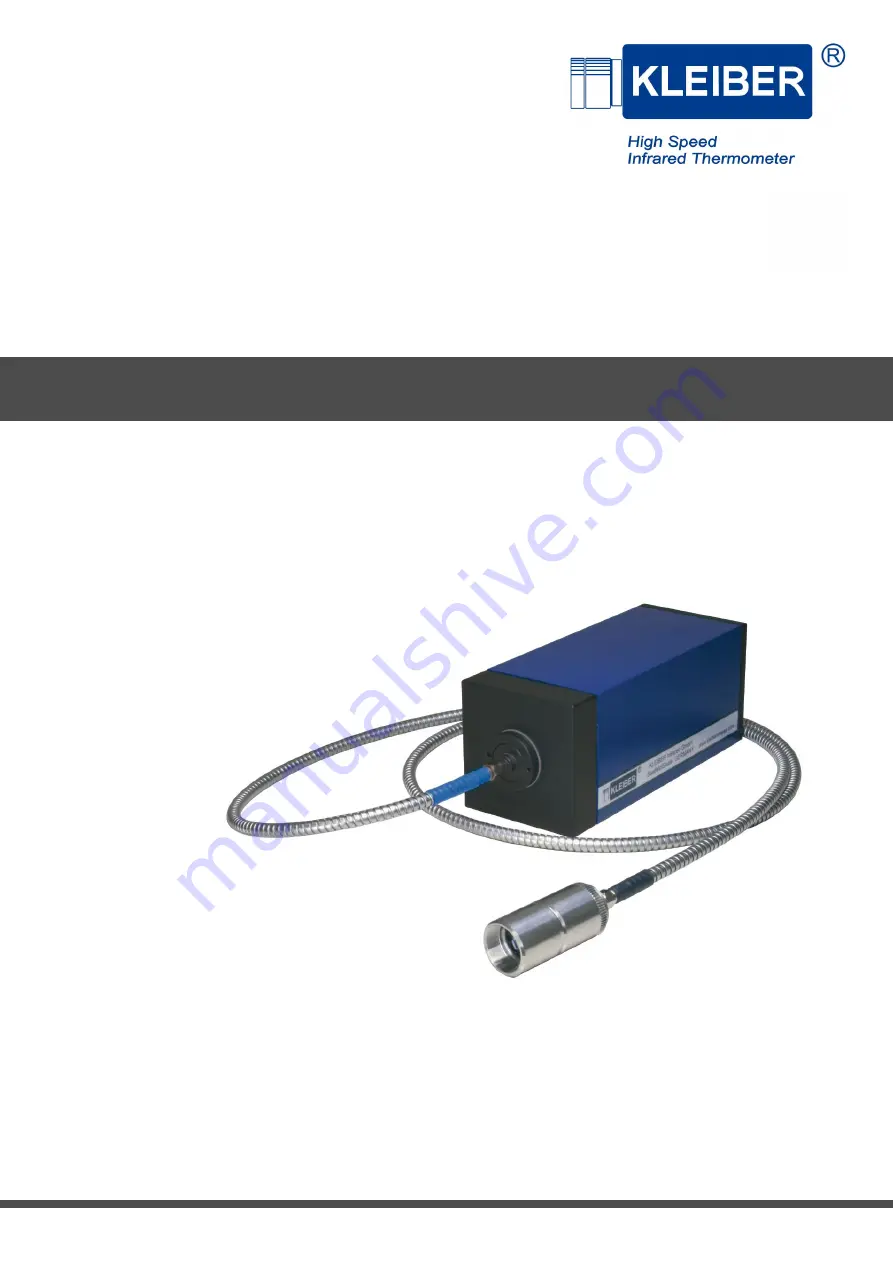
Страница 1: ...KS KG KGA 740 LO KLEIBER Pyrometer Operation Manual Betriebsanleitung Fast measurement fast controlling fast switching...
Страница 2: ...orage on electronic media and translation of the manual into foreign languages without written approval of the company KLEIBER Infrared GmbH is strictly forbidden All rights reserved 2010 2017 KLEIBER...
Страница 3: ...eter 9 5 Technical Description 10 5 1 System Design Principle of Operation 10 5 2 Optics 10 5 2 1 Vario optics 10 5 2 2 Fixed optics 10 5 2 3 Setting the vario fiber optics 11 5 3 Operating elements a...
Страница 4: ...Storage of the Pyrometer 17 9 Maintenance and Care 18 9 1 General information 18 9 2 Cleaning the Optics 18 10 Taking out of service Disposal 19 10 1 Taking out of service 19 10 2 Disposal 19 iv KS K...
Страница 5: ...ems in sub lists are preceded by dashes Safety precautions are shown with pictograms and key words They provide information about the type source and consequences of the hazard and safety precautions...
Страница 6: ...ffers a warranty of 12 months on all repaired and or exchanged instrument components Deviations from the proper use described in this user manual will result in restricted warranty and liability or th...
Страница 7: ...eter is confirmed by the decla ration of conformity and the CE mark All information related to safety is with reference to the regulations of the European Union currently in force In other countries a...
Страница 8: ...0 KS 740 LO Current output 0 20 mA 600 1 600 07400 11400 Current output 4 20 mA 07400 12200 Current output 0 20 mA 800 2 300 07400 12400 Current output 4 20 mA 07401 11200 KG 740 LO Current output 0 2...
Страница 9: ...50 Connecting cable connector straight 5 pol jack 5 pol 15 0 m 30007 51200 Connecting cable connector straight 5 pol jack 5 pol 20 0 m 30007 51900 Extension connecting cable connector straight 5 pol j...
Страница 10: ...and special optics Art No Description 30006 33225 Protection glass 30006 32040 Screw cap incl protection glass very fast changeable 30006 32050 Screw cap incl correction lens very fast changeable onl...
Страница 11: ...cal fiber 200 m red stainless steel 5 0 m 30005 12075 Optical fiber 200 m red stainless steel 7 5 m 30005 12100 Optical fiber 200 m red stainless steel 10 0 m 30005 12150 Optical fiber 200 m red stain...
Страница 12: ...gree of protection IP 54 according to DIN 40 050 Test base EN 55 011 1998 limit class A CE marking According to EU regulations Length 170 mm Height 70 mm Depth 70 mm 4 2 Measurement ranges Type Meas r...
Страница 13: ...C X X X X X X X X X 400 3 000 C X X X X X X X X X X X 350 3 500 C X X X X X B X X X B B Legend X Standard combination B Combination possible with higher effort noise Combination not possible 4 3 Drawi...
Страница 14: ...gnal which can then be read in the display and be used for process control The operating elements as well as the connections interfaces are located at the back of the pyrometer see Operating elements...
Страница 15: ...ntil length L has been reached for the correspondingly measuring distance Mentioned distances in the data sheet are essential to be maintained 4 After adjusting the measuring distance lock the ring nu...
Страница 16: ...voltage 3 Green Ground output 4 Yellow Analog output 0 4 20 mA 5 Green Yellow PE 5 5 Mounting To mount the pyrometer a threaded drilling M12 is located on the underside of the unit The pyrometer can b...
Страница 17: ...eter show the same temperature value X After adjusting the emissivity factor through a correlation measurement you can now measure temperatures for the calibrated temperature range at an accuracy ment...
Страница 18: ...gases 6 1 2 Requirements at the place of use Take into account the following requirements at the place of use of the pyrometer Take care with the choice of the place of use and take into account the...
Страница 19: ...ed to the back of the fiber optics The fiber optics can also fastened with serveral mountings that are available as accessories The minimum bend radius of the optical fiber 200 mm type red 400 mm type...
Страница 20: ...ens Do not undertake any interventions into the pyrometer If problems arise which do not relate to the causes mentioned above inform the service staff of the KLEIBER Infrared GmbH for contact data see...
Страница 21: ...temperature deviations while transporting In the case of overseas shipping a suitable desiccator e g silica gel should be inserted and the pyrom eter should be sealed together with the desiccator in a...
Страница 22: ...tics The optics must therefore be checked and if necessary cleaned at regular intervals according to the operating and environmental conditions see Cleaning the Optics section 9 2 at page 18 This is n...
Страница 23: ...ion as follows 1 Switch off the power supply to the pyrometer 2 Remove the cables at the rear side of the pyrometer 3 Remove the optical fiber at the front side of the pyrometer and from the fiber opt...
Страница 24: ...10 Taking out of service Disposal 20 KS KG KGA 740 LO...
Страница 25: ...8 4 3 Zeichnung Pyrometer 9 5 Technische Beschreibung 10 5 1 Systemaufbau Funktionsprinzip 10 5 2 Optik 10 5 2 1 Variooptik 10 5 2 2 Festoptik 10 5 2 3 Einstellen der Variolichtwellenleitervorsatzopti...
Страница 26: ...RZEICHNIS 8 2 Lagerung des Pyrometers 17 9 Wartung und Pflege 18 9 1 Allgemeines 18 9 2 Reinigen der Optik 18 10 Au erbetriebnahme Entsorgung 19 10 1 Au erbetriebnahme 19 10 2 Entsorgung 19 ii KS KG K...
Страница 27: ...ungen als Strichaufz hlungen dargestellt Sicherheitshinweise sind mit Piktogrammen und einem Signalwort gekennzeichnet Es werden Art Quelle und die Folgen der Gefahr benannt sowie Hinweise zur Gefahre...
Страница 28: ...tur gibt die KLEIBER Infrared GmbH eine Gew hrleistung von 12 Monaten auf alle reparierten bzw ausgetauschten Ger tekomponenten Abweichungen von der in dieser Bedienungsanleitung beschriebenen bestimm...
Страница 29: ...ewandt Die Sicherheit des Pyrometers wird durch die Konformit tserkl rung und die CE Kennzeichnung erkl rt Alle Angaben zur Sicherheit beziehen sich auf die derzeit g ltigen Verordnungen der Europ isc...
Страница 30: ...bereich 07400 11200 KS 740 LO Stromausgang 0 20 mA 600 1 600 07400 11400 Stromausgang 4 20 mA 07400 12200 Stromausgang 0 20 mA 800 2 300 07400 12400 Stromausgang 4 20 mA 07401 11200 KG 740 LO Stromaus...
Страница 31: ...schlusskabel Steckeranschluss gerade 5 pol Buchse 5 pol 15 0 m 30007 51200 Anschlusskabel Steckeranschluss gerade 5 pol Buchse 5 pol 20 0 m 30007 51900 Verl ngerung Anschlusskabel Steckeranschluss ger...
Страница 32: ...r Bezeichnung 30006 33225 Wechselbare Schutzscheiben 30006 32040 Schraubkappe mit Schutzscheibe sehr schnell wechselbar 30006 32050 Schraubkappe mit Korrekturlinse sehr schnell wechselbar nur LVA 25 3...
Страница 33: ...0 m 30005 12075 Lichtleiter 200 m rot Edelstahl 7 5 m 30005 12100 Lichtleiter 200 m rot Edelstahl 10 0 m 30005 12150 Lichtleiter 200 m rot Edelstahl 15 0 m 30005 12900 Verl ngerung Lichtleiter 200 m r...
Страница 34: ...ngsversorgung 24 V DC 0 2 A oder 24 V AC 0 2 A Schutzart IP 54 nach DIN 40 050 Pr fgrundlage EN 55 011 1998 Grenzwertklasse A CE Kennzeichnung Gem EU Richtlinien L nge 170 mm H he 70 mm Tiefe 70 mm 4...
Страница 35: ...400 3 000 C X X X X X X X X X X X 350 3 500 C X X X X X B X X X B B Legende X Standardkombination B Kombination mit h heren Auf wand Rauschen m glich Kombination nicht m glich 4 3 Zeichnung Pyrometer...
Страница 36: ...al umgewandelt Es kann dann zur Anzeige gebracht und zur Steuerung oder Regelung verwendet werden Die Bedienelemente sowie die Anschl sse Schnittstellen befinden sich an der R ckseite des Pyrometers v...
Страница 37: ...und drehen Sie das Geh use soweit bis die L nge L f r den entsprechenden Messabstand erreicht ist Die im Datenblatt genannten Abst nde sind unbedingt einzuhalten 4 Arretieren Sie nach dem Einstellen d...
Страница 38: ...luss 5 poliges Kabel Anschluss Farbe Kabe lader Bedeutung 1 Wei 24 V AC DC Versorgungsspan nung 2 Braun 0 V AC DC Versorgungsspannung 3 Gr n Masse Ausgang 4 Gelb Analogausgang 0 4 20 mA 5 Gr n Gelb PE...
Страница 39: ...das Pyrometer auf das Messobjekt und stellen Sie den Emissionsgrad so ein dass beide Ger te Pyrometer und Kontaktf hler den gleichen Temperaturwert anzeigen X Der Emissionsgrad ist damit ber eine Verg...
Страница 40: ...hten Sie folgende Anforderungen an den Einsatzort des Pyrometers Beachten Sie bei der Wahl des Einsatzortes ergonomische und arbeitsschutzrechtliche Richtlinien um eine sichere Bedienung des Pyrometer...
Страница 41: ...angeschlossen Das schwarze Ende des Lichtwellenleiters wird an die R ckseite der Lichtwellenleitervorsatzoptik angeschlossen Die Lichtwellenleitervorsatzoptik kann mit verschiedenen Halterungen die a...
Страница 42: ...r ckzuf hren sind Nehmen Sie keine Eingriffe in das Pyrometer selbst vor Treten St rungen auf die sich nicht auf die oben ge nannten Ursachen zur ckf hren lassen verst ndigen Sie das Servicepersonal d...
Страница 43: ...en Bei berseeversand ist ein geeignetes Trockenmittel z B Silikagel beizulegen und das Pyrometer ist zusammen mit dem Trockenmittel in eine Folie einzuschwei en Wird das Pyrometer nicht unmittelbar na...
Страница 44: ...ss deshalb entsprechend den Betriebs und Umgebungsbedingungen in regelm igen Abst nden berpr ft und ggf gereinigt werden vgl Reinigen der Optik Abschnitt 9 2 auf Seite 18 Dies ist insbesondere dann no...
Страница 45: ...ter wie folgt au er Betrieb 1 Schalten Sie die Spannungsversorgung des Pyrometers aus 2 Entfernen Sie die Anschlusskabel an der R ckseite des Pyrometers 3 Entfernen Sie den Lichtwellenleiter an der Vo...