44
7.3
Pendant
7.3.1
The following procedure covers the installation of the Pendant Hose (Parts List Figure Number 360)
and the Pendant Valve. Refer to Figure 7-6.
1)
Place boot on the ends of the Pendant Hoses to be attached to the Manifold Block on the hoist.
2)
Attach pendant hose to hoist body using the one-piece fittings and screw type clamps (hose
bands).
3)
Attach pendant hoses to the pendant valve using the 2 piece fittings and crimp type hose clamps
(hose bands). Refer to Figure 7-6 for the correct placement of the Hoses.
4)
Attach the Strain Relief wire S-Hook on the Pendant Valve and Manifold Block using the S-Hook.
5)
Slide the Boot in to place over the Hose Fittings at the Manifold Block on the hoist.
6)
!
CAUTION
Operate hoist and make sure the direction of hook travel agrees with the
control levers on the Pendant Valve.
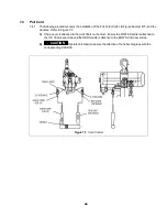
Figure 7-6
Pendant Hose Connections
Содержание TCL Series
Страница 43: ...43 Figure 7 4 Single Fall Chain Connections Figure 7 5 Double Fall Chain Connections ...
Страница 52: ...10 1 Motor Valve Body and Controls 52 Figure 10 1 Motor Valve Body and Controls ...
Страница 55: ...55 This Page Intentionally Left Blank ...
Страница 56: ...10 2 Brake Gears and Load Suspension Components 56 Figure 10 2 Brake Gears and Load Suspension Components ...
Страница 61: ...61 NOTES ...
Страница 62: ...62 NOTES ...
Страница 63: ...63 NOTES ...

