


Page
10
4. Installing the Unit
WARNING: Explosion hazard!
•
DO NOT install the unit near flammable fumes or gases (such as propane tanks or large engines).
•
AVOID covering the ventilation openings. Always operate unit in an open area.
Choosing the location:
The unit should only be installed in locations that meet the following requirements:
•
Do not allow water or other fluids to drip or splash on the unit.
•
Environment temperature should be between -4 °F and 104 °F (-20 °C and 40 °C)
•
Allow at least three inches of clearance around the unit. The more clearance for ventilation around
the unit, the better the performance.
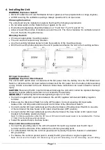
Mounting the Unit:
•
Choose an appropriate mounting location.
•
The unit can be mounted in any direction.
•
Use the mounting template below to mark the positions of the mounting screws.
•
Drill the 4 mounting holes and place the unit in position and fasten the unit to the mounting surface.
DC Input Connection:
WARNING: Electrical Shock Hazard
The unit ‘On/Off’ switch does not disconnect the DC power from the battery. Use the DC Disconnect
Switch or disconnect the DC input cables to disconnect the DC power from the battery before working
on any circuits connected to the unit. Failure to follow these instructions can result in death or serious
injury.
CAUTION:
Reversing the DC Input terminals will damage the unit and it cannot be repaired. Damage
caused by reverse polarity connection is not covered by the warranty.
IMPORTANT:
Field wiring DC terminals tightening torque 12-13 Nm
•
Connect a negative DC input cable between the unit DC negative terminal and battery negative
terminal.
•
Make sure the Disconnect Switch is in the OFF position. Connect a positive DC input cable
between the unit DC positive terminal and one terminal of the Disconnect Switch.
•
Connect another DC input cable between the other terminals of the Disconnect Switch to one side
of the terminal of the fuse holder or DC rated circuit breaker (OFF position).
•
Connect another DC input cable between the other terminal of the fuse holder or DC rated circuit
breaker to the battery positive terminal.
Note: For Marine application, either the DC fuse or DC rated circuit breaker needs to be installed within 7 inches
(17.8cm) from the battery positive terminals.
•
Install the selected fuse to the fuse holder.
Chassis DC Ground Connection:
•
Connect the grounding wire to the unit’s Chassis DC Ground Lug located near the DC Input
terminal and the other side of the cable to the common grounding point.
•
For a Recreation Vehicle, the common ground point is usually the vehicle chassis or a dedicated
DC ground bus.
•
For Marine, the common ground point is usually the DC ground bus or engine negative bus.
Note: Do not use the Chassis DC Ground Lug for your AC Grounding, For AC Grounding, see AC Wiring


