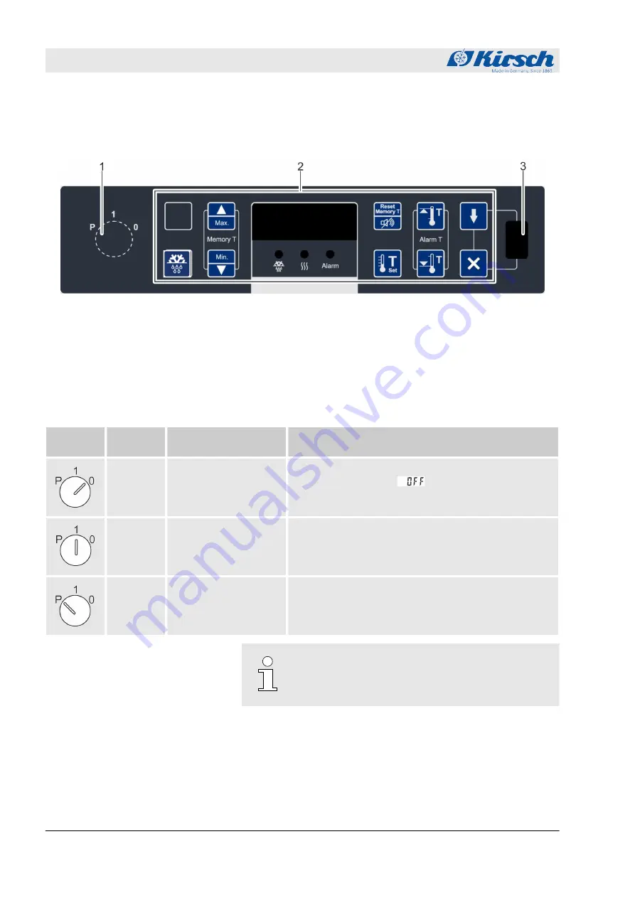
1.2 Display and control elements
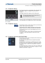
1.2.1 Design of the display and control unit
Fig. 5: Display and control unit
1
Key switch
2
Display and control unit (variable key assignment)
3
USB port
1.2.2 Function of the key switch
Tab. 1: Position of the key switch
Key posi-
tion
Position
Function
Description
“0”
Switch off unit.
n
Switch off unit (for example to perform a restart).
n
The Display shows
.
n
To put the unit in a currentless state, unplug the
power plug.
“1”
Switch on unit.
n
Operate unit.
n
Display and reset unit values (for example actual
temperature or temperature limits).
n
Confirm alarms.
“P”
Program unit.
n
Adjust unit (for example target values or temperature
warning limits).
n
Display parameter lists.
n
Confirm alarms.
Always operate unit in key position “1” in order to
prevent manipulation. During normal operation,
remove key and store it safely.
1.2.3 Function of buttons and displays
For the functions of buttons and displays, see the following over-
view:
Product description
Display and control elements > Function of buttons and displays
26.05.2021
Refrigerator/freezer BL series
12


