


ADJUSTMENTS
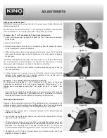
ADJUSTING BELT PLATEN (1” OR 2” BELT PLATENS)
The belt platen (A) Fig.15 is used to support the workpiece against the sanding belt
during operations. For most common operations using the sanding belt, belt platens
(1” belt platen with 1” x 42” belt, 2” belt platen with 2” x 42” belt) must be adjusted so
that it almost touches the back of the sanding belt. This is done by loosening cap
screw (B) and positioning the belt platen (A) to the desired position.
For not so common operations such as contour sanding or polishing, the belt platen
(A) Fig.15 can be removed. Once the operation is complete, the appropriate belt
platen should be reinstalled.
REPLACING SANDING DISC
WARNING!: Disconnect the power cord from the power source before attempting to
replace a sanding disc.
1. Loosen and remove both disc table lock handles and then remove disc table.
2. Remove disc dust chute as shown in Fig.16 by removing the 6 pan head screws
that secure the dust chute.
3. Peel off the used 8” sanding disc (A) Fig.16. Once remove, clean the aluminum
disc. Make sure the aluminum disc is perfectly clean and dry before attempting to
install a new sanding disc.
4. Peel off the rear backing of the new sanding disc, carefully position the new
sanding disc so it is centered on the aluminum disc. Firmly press the sanding disc
onto the aluminum disc.
5. Reinstall dust chute, disc table and lock handles.
REMOVING ALUMINUM DISC
WARNING!: Disconnect the power cord from the power source before attempting to
remove the aluminum disc.
If needed, the aluminum disc can be removed to simplify the cleaning of the aluminum
disc. To remove the aluminum disc:
1. Loosen and remove both disc table lock handles and then remove disc table.
2. Remove disc dust chute as shown in Fig.16 by removing the 6 pan head screws
that secure the dust chute.
3. Rotate the aluminum disc until the locking set screw (A) Fig.17 is visible through
the opening behind the disc housing. See Fig.17. If the set screw is not accessible
from the opening, it might be needed to move the disc housing forward to gain
access to the set screw.
4. Loosen set screw (A) Fig.17 and pull the aluminum disc (B) out of the disc
housing.
5. Make sure the keyway (A)
Fig.18 on the motor shaft (B) is properly seated before
attempting to reinstall the aluminum disc.
6. Once you have completed the cleaning of the aluminum disc, slide aluminum disc
all the way onto the motor shaft and retighten set screw (A) Fig.17.
Figure 15
Figure 16
Figure 17
Figure 18