34
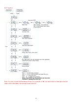
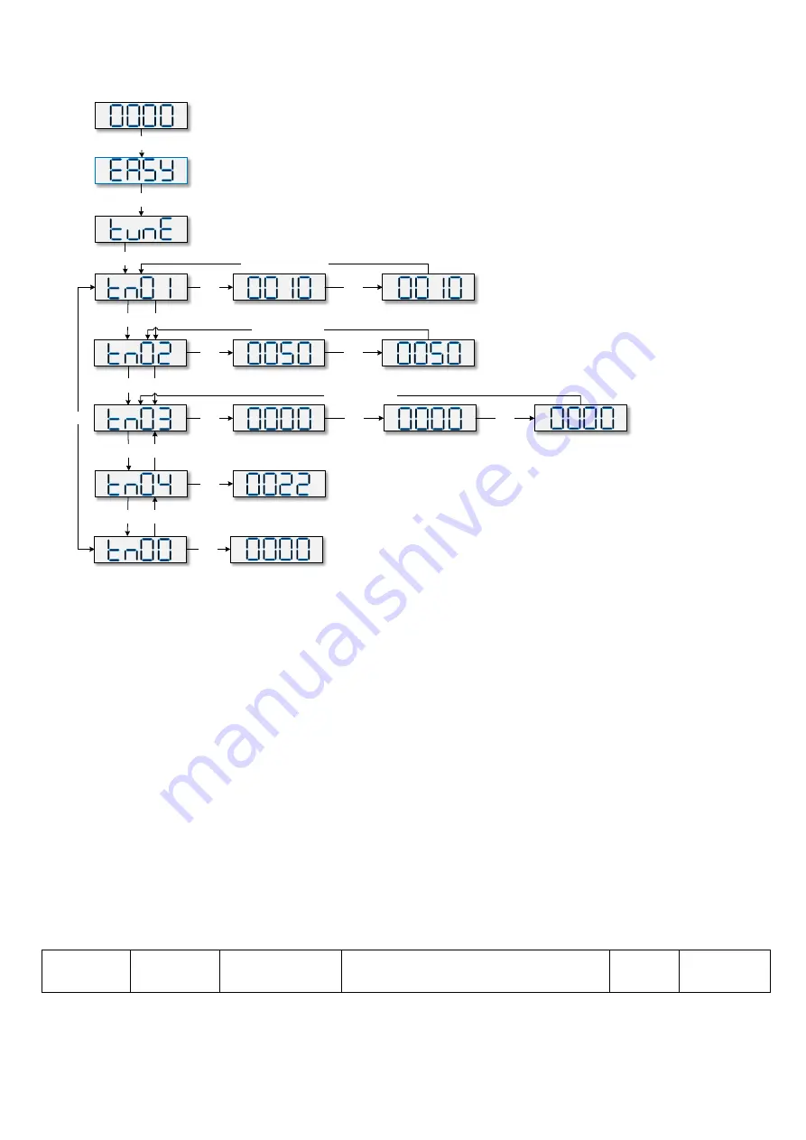
Flowchart for the TunE menu
SET
▲
▼
▲
▼
▲
▼
▲
Stiffness
Write
“
1
”
to start
inertia ratio measuring
Measuring Distance,unit is 0.01 cycle
Inertia ratio, unit is 0.1
Write 1 to save all the parameters
Write 2 to save all the parameters and restart servo
MODE
MODE
Circle
SET
SET
Long Press MODE
▼
LED is blinking,
Press MODE can shift.
the parameters below
display in the same way.
Confirm the parameter ,the
first dot on the right will
lighten. the parameters below
display in the same way.
SET
SET
SET
SET
SET
SET
adjusted by “
▼▲
”level by level
and will be valid immediately
SET
Long Press MODE
Long Press MODE
Write automatically after inertia measuring.
Or written by user. adjusted by “
▼▲
”level by
level and will be valid immediately
Note: Note: Data inputted are valid at once, but must be saved via Tn00.
Considering about safety, it is unnecessary to press "SET" to verify when users need to modify stiffness or inertia
ratio. Data are also valid but are only adjusted step by step.
5.4 Description of Parameters
Group F000 represents an instruction group, and the parameters in this group cannot be saved.
The address d4.00 is used to save the motor parameters set for Group F004. Note that this group of
parameters must be set when customers choose third-party motors, but these parameters need not to be set
for the motors delivered and configured by our company. d2.00, d3.00 and d.5.00 represent the same
address, and are used to save all setup parameters except those of motors (Group
F001/F002/F003/F004/F005). Three numeric objects (d2.00/d3.00/d5.00) are developed to facilitate
customers.
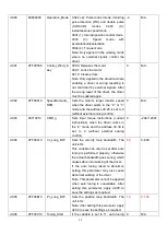
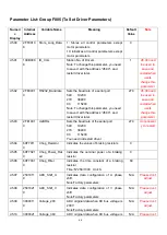
Parameter List: Group F000 (To Set Driver Instructions)
Numeric
Display
Internal
Address
Variable Name
Meaning
Default
Value
Range
Содержание CD2S Series
Страница 7: ...7...
Страница 8: ...8 1 3 3 Power Brake and Encoder cable of Motors...
Страница 12: ...12 Fig 2 3 Installation direction...
Страница 15: ...15 3 1 2 Wiring Diagram Fig 3 1 Wiring diagram of CD2S driver...
Страница 16: ...16 3 1 3 X1 interface of CD2S Driver Fig 3 2 X1 interface Fig 3 3 Wiring diagram of X1 interface...
Страница 23: ...23 Fig 4 3 Separate regulation of bits...
Страница 82: ...82...
Страница 96: ...96 8 4 Debugging example 8 4 1 Oscilloscope 1 Enter oscilloscope 2 Parameters for Oscilloscope...
Страница 98: ...98 In Auto Reverse mode Kvp 110...
Страница 100: ...100 The oscilloscope is as following max following error is 69 inc Fig 2 Kpp 30 Vff 100...
Страница 101: ...101 The oscilloscope is as following max following error is 53 inc Fig 3 Kpp 30 Vff 50...
Страница 102: ...102 The oscilloscope is as following max following error is 230 inc...


