105
9.2.2 Upload(From Slave to Host)
Upload refers to that the master sends a command to read object address in the slave and the master will
generate an error if a non-existent target address is uploaded.
The master sends:
CMD
byte 0 byte 1 byte 2 byte 3 byte 4 byte 5 byte 6 byte 7
INDEX
SUB
INDEX
RESERVED
CMD
Specifies the direction of data transfer
40(0x16)
INDEX
16-bit value
SUBINDEX 8-bit subindex
RESERVED
Bytes 4…7 not used
The slave receives:
RES
byte 0 byte 1 byte 2 byte 3 byte 4 byte 5 byte 6 byte 7
INDEX
SUB
INDEX
DATA
RES
Displays slave response:
43(0x16)
bytes 4...7 contain 32-bit data
4B(0x16)
bytes 4, 5 contain 16-bit data
4F(0x16)
byte 4 contains 8-bit data
80(0x16)
error, bytes 4…7 contain error cause
INDEX
16-bit value, same as that sent by the master
SUBINDEX 8-bit value, same as that sent by the master
If the data contains no error, byte 4…byte 7 save the object value read from the slave, with the lower-order
bits arranged before the higher-order bits. Correct value = byte7, byte6, byte5, byte4. If there is an error, data
contained in these four types is no longer object values read from the slave.
For example:
The master sends a ―upload‖ command to the slave:
01 40 F0 2F 09 58 02 00 00 3D (This command reads target velocity 2FF00910 from the slave)
The slave answers:
01 4B F0 2F 09 58 02 00 00 32
Indicates: 01
—Slave index is 1. 4B – Received data contains 2 bytes, saved to byte 4…byte 5 in the 10
bytes of the response. byte4=58, byte5=02, byte6=00, byte7=00. Then, DATA= byte7 byte6 byte5 byte4 =
0258(hex)= 600 rpm
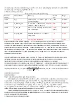
Example 9-1: Use home mode/position mode/speed mode by communication
Home mode
(
Controlword F to 1F)
CANOpen
Name
Value
Message
(
ID=1
)
Meaning
60400010
Controlword
F
01 2B 40 60 00 0F 00 00 00 25
Homing_Speed_Swit
ch
and
60600008
Operation_mode
6
01 2F 60 60 00 06 00 00 00 0A
Содержание CD2S Series
Страница 7: ...7...
Страница 8: ...8 1 3 3 Power Brake and Encoder cable of Motors...
Страница 12: ...12 Fig 2 3 Installation direction...
Страница 15: ...15 3 1 2 Wiring Diagram Fig 3 1 Wiring diagram of CD2S driver...
Страница 16: ...16 3 1 3 X1 interface of CD2S Driver Fig 3 2 X1 interface Fig 3 3 Wiring diagram of X1 interface...
Страница 23: ...23 Fig 4 3 Separate regulation of bits...
Страница 82: ...82...
Страница 96: ...96 8 4 Debugging example 8 4 1 Oscilloscope 1 Enter oscilloscope 2 Parameters for Oscilloscope...
Страница 98: ...98 In Auto Reverse mode Kvp 110...
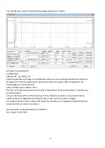
Страница 100: ...100 The oscilloscope is as following max following error is 69 inc Fig 2 Kpp 30 Vff 100...
Страница 101: ...101 The oscilloscope is as following max following error is 53 inc Fig 3 Kpp 30 Vff 50...
Страница 102: ...102 The oscilloscope is as following max following error is 230 inc...


