Cetra
®
1
Proper product installation, in accordance with these instructions, is the responsibility of the installing agent.
If you have any questions concerning these instructions, please call Kimball Office Customer Care.
2382137 Revision A
Assembly Instructions
5. Tighten screws until the “U” channel is tight against the
Traxx (figure B).
Note:
The top edge of the “U” channel should be even with the
top of the upper Traxx when the panel is the same height of the
upper Traxx.
Starter Panel Installation
Tools Required
Package Contents
Tape Measure
Level 4 ft. or greater
Philips screwdriver
Wall fastener
Fastener tool
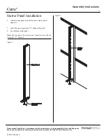
1. Install the 1/4” X 20 X 1/2” Phillips pan head screws
through the holes on the inside of the “U” channel (figure
A)
Note:
For Panels Less that upper Traxx height use secondary
fastening (figure A1)
Note:
Wall fasteners and hole location are the responsibility of
the Installer
Installation
U channel
Starter Panel
1/4” X 20 X 1/2” Phillips pan head screw
1/4” X 20 weld nuts
Figure A Figure A1
Figure B
Dry Wall:
Must be at least 5/8" thick. Use 3/16" hollow wall
fasteners or 3/16" toggle bolts with countersunk flat head ma-
chine screws.
Wood Studs:
Must be nominal 2" x 4" size, on no more than
24" center with maximum height of 14 feet restrained at floor
and ceiling. Use #10x2" countersunk flat head screws.
Metal Studs:
Must be "C" channel, 20 gauge, on no more
than 24" center. Maximum height of 14 feet restrained at
floor and ceiling. Use 3/16" hollow wall fasteners or 3/16"
toggle bolts with countersunk flat head machine screws.
Concrete: Use concrete wall anchors with #10x11/2" counter-
sunk flat head machine screws.
Recommended Fasteners
2. Hand turn the 1/2” x 20 weld nuts onto the screws (figure
A). Orient weld nut horizontally to allow insertion into
Traxx. Do not tighten.
3. Position the starter panel “U” channel against Traxx at
desired location (figure B).
4. Level/plumb the “U” channel (figure B).


