SIRIUS CAPACITOR MODULE
User Manual
Model number: 3550-48-B-1.7C-TM-SD-A-19G
Version 1.0; Release Date: August 2019
Author: Mamoona Khalid
Страница 1: ...SIRIUS CAPACITOR MODULE User Manual Model number 3550 48 B 1 7C TM SD A 19G Version 1 0 Release Date August 2019 Author Mamoona Khalid ...
Страница 2: ... change without notice While every attempt has been made to make the Manual accurate and up to date users are cautioned that product improvements may cause the Company to make changes to specifications without advance notice Users are encouraged to consult the Company or its Resellers before using the Manual Neither the Company nor its Resellers shall be liable for any indirect incidental or conse...
Страница 3: ...erview 8 2 2 1 Appearance 8 2 2 2 Mechanical Drawings 9 2 2 3 Dimensions and Weight 11 2 3 Product Description 11 3 Module Installation 15 3 1 Inspection 15 3 2 Safety Gear 15 3 3 Unpacking and Contents Check 16 4 Operation Procedures 16 4 1 Module Configuration 16 4 2 Software Configuration 18 5 Recovery Procedure 21 6 Connecting the Module in Parallel or in Series 23 6 1 Parallel Connection of S...
Страница 4: ... 19G This manual is subject to change without notice and at the sole discretion of Kilowatt Labs Inc Kilowatt Labs Inc www kilowattlabs com 4 13 Test Procedures 29 13 1 Round Trip Efficiency Test 29 13 2 Performance Data 30 13 3 Test Method for Self Discharge 31 14 FAQs 32 ...
Страница 5: ... Sirius Modules are designed to provide years of trouble free operation Proper handling is required to avoid damage to the Module In particular the following precautions should be observed Personal Safety Always wear proper personal protective equipment eyes protection gloves and safety shoes Always make sure charger is set as recommended Always make sure chargers are disconnected while working on...
Страница 6: ...to prevent short circuit under all circumstances Do not connect or disconnect terminals from the Module without first disconnecting the load Do not touch the terminals with conductors while the Module is charged Serious burns shock or material fusing may occur Protect surrounding electrical components from incidental contact When connecting to external devices ensure that galvanic isolation does n...
Страница 7: ... wrap and open the carton box and lift the Module manually If the Modules are shipped via Sea please follow the instructions below Carefully remove the Module from the pallets after cutting the packing strip holding the Modules to the shipping pallets Open the carton box and lift the Module manually 1 5 Qualified Installer Selling and installation of this Module is only through the Company s Resel...
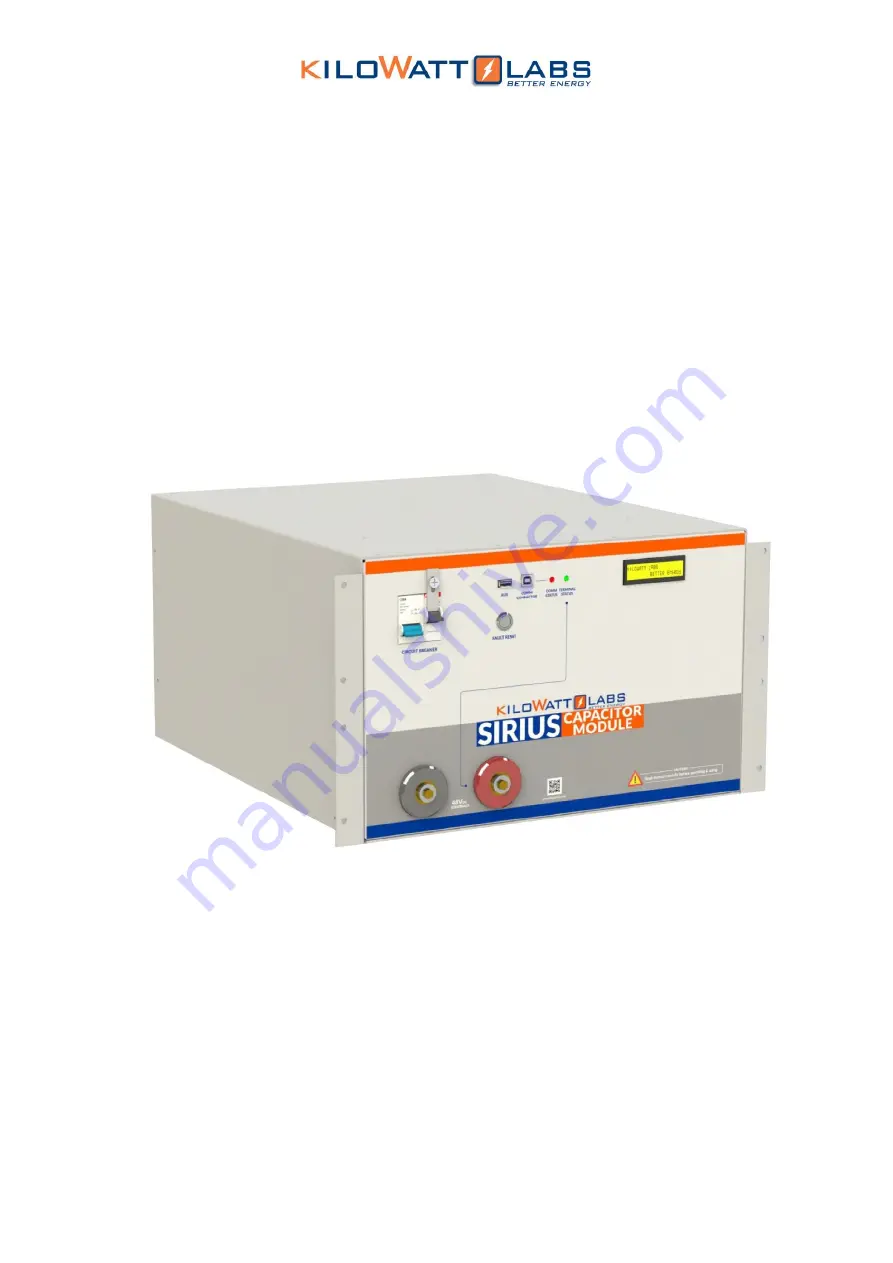
Страница 8: ...550 48 B 1 7C TM SD A 19G This manual is subject to change without notice and at the sole discretion of Kilowatt Labs Inc Kilowatt Labs Inc www kilowattlabs com 8 2 2 Product Overview 2 2 1 Appearance The appearance of the Sirius Module is shown below ...
Страница 9: ...Manual Model Number 3550 48 B 1 7C TM SD A 19G This manual is subject to change without notice and at the sole discretion of Kilowatt Labs Inc Kilowatt Labs Inc www kilowattlabs com 9 2 2 2 Mechanical Drawings Front View Side View ...
Страница 10: ...odule User Manual Model Number 3550 48 B 1 7C TM SD A 19G This manual is subject to change without notice and at the sole discretion of Kilowatt Labs Inc Kilowatt Labs Inc www kilowattlabs com 10 Top View Isometric View ...
Страница 11: ... 60 mm Depth 530 mm Height 270 mm weight 65 kg 2 3 Product Description Object Mark Description 1 Circuit Breaker C100A Circuit breaker for switch ON OFF Module 2 Bypass Circuit Breaker C20A Circuit breaker for bypassing electronic switch 3 Fault Reset Fault Reset Button 4 Aux Auxiliary USB 5 Comm Connector Communication Connector USB 6 Comm Status Communication Status LED 7 Terminal Status Termina...
Страница 12: ...he terminals manually after it turns OFF due to any error The additional features of fault reset are as follows a Hold fault reset for 5 seconds to toggle the terminal b Hold fault reset for 3 seconds to reset fault if there is are any c Press fault reset button to check the state of charge and instantaneous power d We can set the Current reading to zero To make the current zero follow the steps b...
Страница 13: ...lt reset button once more or leave the Module idle for 5 seconds 4 Auxiliary USB This is an auxiliary connector with isolated UART or Serial Communication for wireless monitoring Module Combiner and future functions 5 COMM Connector USB This is a COMM connector to monitor the Module using the Sirius software FTDi chip is used for this USB 6 COMM Status LED COMM Status LED indicates the communicati...
Страница 14: ...D Terminal status LED indicates the F12 terminal status Color Status Indication Green ON The F12 terminal is active Green OFF The F12 terminal is not active 8 LCD Description Once the power is switched ON from the circuit breaker the Module gets power and the LCD shows the following message After the password is entered the LCD will show the following message After 1 second the following two LCD s...
Страница 15: ...le Document photograph any damage and report this to your Reseller as well as to the shipping agent immediately Remove the Module from the shipping carton and retain the shipping materials until the unit has been inspected and is determined to be operational 3 2 Safety Gear Installation must strictly follow the national safety regulations in compliance with the enclosure installation creepage clea...
Страница 16: ...www kilowattlabs com 16 3 3 Unpacking and Contents Check Check the contents of the package 1 Sirius Capacitor Module 3 55KWh48VDC 3 USB Cable A B 2 Screws 2 4 Washers 4 4 Operation Procedures 4 1 Module Configuration Follow the steps below to switch ON the Module Step 1 Connecting the Load Connect the F12 terminals of the Module to the load F12 terminals are shown in picture below 1 2 3 4 ...
Страница 17: ...bs com 17 Step 2 Module Start Up 1 Turn ON the Circuit breaker by pushing the Blue button upwards as shown in the picture below 2 The picture below shows that the Module is turned ON 3 Wait till the LCD screen on the Module displays initial values 4 Be sure you are able to see the terminal status LED OFF Note Use the Bypass circuit breaker button to connect the Modules in Series and for recovery p...
Страница 18: ...he OFF position 4 2 Software Configuration To configure Sirius VIEW application please follow the steps below 1 Install the Sirius VIEW application on your system 2 Connect the USB cable to the COMM connector USB slot to start communication and monitoring 3 Turn on the Sirius Module by pressing the fault reset button on front panel 4 Wait till the LCD screen on the Module displays initial values 5...
Страница 19: ... to change without notice and at the sole discretion of Kilowatt Labs Inc Kilowatt Labs Inc www kilowattlabs com 19 7 By clicking on Login the below pop up messages will appear 8 Keep on clicking OK until Sirius VIEW Monitoring Software window appears as shown below Select Sirius VIEW and left click ...
Страница 20: ...button on interface Auto Pop up dialogs 10 When the connection between PC and Module is established successfully INIT LED will be constantly turned ON 11 For getting measurement press RUN button 12 If there is any problem during connection check USB cable and ensure the Module is working properly 13 While getting measurement MEASURING LED should blink every 1 second If blinking has stopped it will...
Страница 21: ...Module ON as shown below 2 A power supply having voltage range of 44Vdc to 54Vdc and current range of 1A to 10A will be required 3 Connect the positive terminal of the power supply to the positive terminal of the F12 terminal and negative terminal of the power supply to the negative terminal of the F12 terminal 4 Remove the lock screw from the Bypass Circuit breaker with the help of screw driver 5...
Страница 22: ... and at the sole discretion of Kilowatt Labs Inc Kilowatt Labs Inc www kilowattlabs com 22 6 The event may take several minutes depending on the power supply used 7 At this stage remove the power supply and leave the Module for normal recharge Recommended Charger for Recovery Maximum Current 10 A Recommended Voltage 44V 55V ...
Страница 23: ...Modules Any number of Modules can be connected in parallel Steps to Connect Modules in Parallel Refer to the parallel combination of the Sirius Modules as shown below and make your connection accordingly Connect the positive of the F12 Terminal of all Modules Connect the negative of the F12 Terminal of all Modules Take out the output positive and output negative from the respective common point Ca...
Страница 24: ...erminal of the first Module with the positive of the F12 terminal of the next Module Take the Output Positive from first Module and Output Negative from the last Module Caution Charge all the Modules to 100 SOC or same voltage level before connecting them in Series Note Switch ON the bypass Circuit breaker when connecting in Series otherwise it will damage the electronic switch Note Modules cannot...
Страница 25: ... the cut off and count down has reached to zero the buzzer alarms and the electronic switch will shut down Module Charge Full When the Module voltage reaches the maximum voltage the electronic switch will shut down This means that each cell from the Module has reached to maximum rated charge The event will be repeated if the charger is still ON and operating in the same condition the buzzer alarms...
Страница 26: ...when the current goes above 125A or when the Module is short circuited In this event the electronic switch will shut down Switch OFF the circuit breaker and check the continuity across the Module terminals to find whether there is a short circuit In case of a short circuit check the operating circuitry and clear the short circuit Over Temperature OT OT occurs when the Module temperature goes above...
Страница 27: ...ule has LCD and Fault Reset Button The fault reset button acts as a multifunction button for monitoring and configuration By using Reset fault Button and LCD user can Turn ON OFF terminals of Module Read Cell Voltages Instantaneous Power SOC Terminal Voltage Terminal Current Terminal Temperature and Ambient Temperature Recalibrating Current Measurement by configuring zero current values Activating...
Страница 28: ... Sirius VIEW Monitoring Application 5 Sirius Module has one of the best ADC to increase measurement accuracy up to 6µV level 6 Sirius Module has advanced algorithm to control Module in safest way This algorithm can be upgraded by user with updating firmware of Sirius Module over Sirius VIEW Monitoring 7 Sirius Module firmware can be customized easily based on user needs 8 Sirius Module has USB int...
Страница 29: ...iciency characterization Test Equipment DC Charger test system or any other test system which can be used to charge and discharge Module with test cycle programing We used WRL48V80A27cd DC Charger Motor for charging and WRL FDY48L20 Battery Discharge Tester for discharging Test Temperature Room temperature 23o C 2o C Temperature controlled chamber can be used if testing at any environment other th...
Страница 30: ...scharge energy E2 total charge energy E1 100 13 2 Performance Data It can be seen from the graph that as charge current is increased the time required for making Module full charge is decreased The Module behavior with different charge currents is quite similar Total voltage level dramatically increases from 46V to 47 5V in less than 2 minutes and have linear behavior between 48V to 53V There is v...
Страница 31: ... voltage Vmax Step2 Leave the battery idle for a period of 1 month Record the open circuit voltage after 1 month Voc It can be seen from the graph that as discharge current rate is increased the time required to discharge the Module is decreased Similar to Module charge graph also while discharging there is dramatic voltage decrease from 53V to 50V in less than 9 minutes regardless of discharge cu...
Страница 32: ...oint that it will not charge without some sort of manual recovery A Getting Module totally empty zero voltage after leaving the Module stand by for long time is normal so in this case LCD electronic switch will be OFF but the Module can be recovered Please refer to recovery procedure in the user manual Q Self consumption of the Module when connected to a power source and the terminal is ON seem to...
Страница 33: ...charge controller systems inverter end to 45V will that allow the Module to sit at idle for longer periods of time to avoid an undervoltage situation A Yes Q Which is most compatible charge controller systems inverter and whether any charge controllers have been integrated with Sirius in this application A All charge controllers that are compatible with our Module specification please refer to use...
Страница 34: ...s switched OFF and the Sirius VIEW is still open you have to wait for 10 Sec since the application is still communicating with the Module before turning ON the Module or either by terminating the Sirius VIEW or by disconnecting the communication cable Q How much is the capacity of the internal storage SD Card A 8GB SD Card is used in the Module which logs 85 bytes of data per 10 seconds Note that ...
Страница 35: ... to use anther USB cable Try to use anther port in the PC Check the Module USB drive in your PC from setting then search for Device Manager then go to ports as shown below Please refer to USB serial driver quick install After the troubleshooting if the problem still doesn t solve please consult with your Reseller Q The Module is showing Contact Service A Contact your Reseller for customer support ...
Страница 36: ...be activated from any voltage level when the Module is in standby mode Zero current When all the cells get balance the balancing will stop The time required to balance all cells depends on cells condition Auto balancing Auto balancing is activated automatically during charging when the cells get unbalanced Note that it is activated only when the Module Voltage reaches 52 V Q Can balancing and auto...