Interface Setup
KIKUSUI Electronics Corp.
PWR-01 Interface Manual
■
RS232C communication
The PWR-01 does not have flow control (this is fixed). If you send setting com-
mands consecutively at a high speed, the PWR-01 reception buffer may overflow.
Do not send setting commands consecutively. Send query commands and read the
responses at a certain interval, or reduce the command transmission frequency.
■
Break signal
The break signal functions as a substitute for the IEEE488.1 dcl / sdc (Device
Clear, Selected Device Clear) message.
- Note -
The RS232C interface should be shifted remotely by the command. Use the
"
" SCPI command to set the RS232C interface to the remote
state. Be sure to include this command at the start of the program when you are
performing remote programming.
USB
A device driver supporting USB T&M Class (USBTMC) is required to control the
PWR-01 through the USB interface. The USBTMC driver is automatically installed
by the VISA library.
■
USB connection
Use a standard USB cable to connect the PWR-01 to the PC.
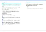
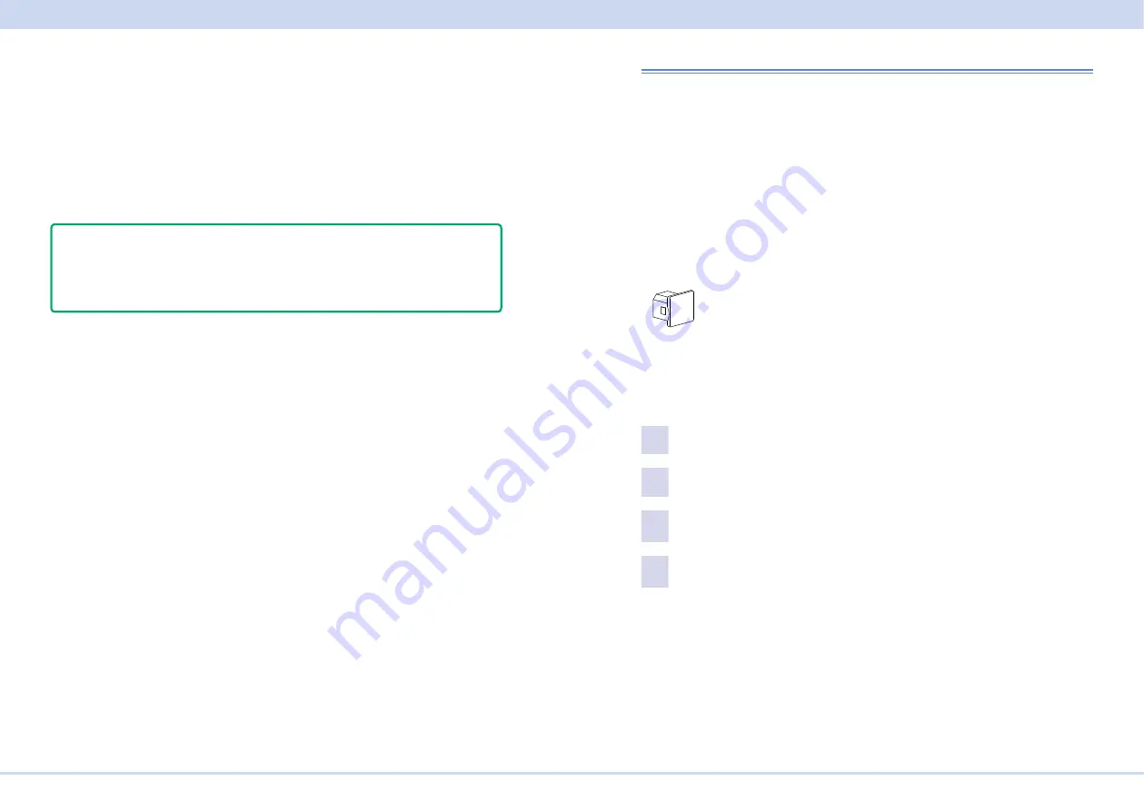
The USB port of this product comes with a cover. Remove the cover to use the
port. Store the cover in a safe place so that you can use it to cover the USB port
when the port is no longer in use. For safety reasons, when not using the USB port,
be sure to attach to cover. For safety reasons, when not using the sensing termi-
nals, be sure to attach to terminal cover.
Port cover
[P1-000-132]
■
USB setting
The factory default USB setting is “USB enabled.”
For datails of CONFIG settings, see the PWR-01 user's manual.
1
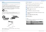
Press CONFIG several times until CF40 is displayed.
2
Turn the VOLTAGE knob until CF41 (USB interface setting) is displayed.
3
Use the CURRENT knob to select ON.
USB is enabled.
4
Restart the PWR-01.
The settings are applied.
■
Service request
The PWR-01 is equipped with service request and serial polling functions.

