background image

KIKUSUI ELECTRONICS CORP.

http://www.kikusui.co.jp/en

1-1-3 Higashiyamata, Tsuzuki-ku, Yokohama, 

224-0023, Japan

Tel: +81-45-593-7570    Fax: +81-45-593-7571

Website

Содержание PAS 10-105

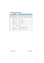
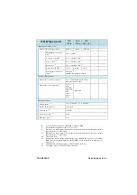
Страница 1: ... PAS 10 35 PAS 20 18 PAS 40 9 PAS 60 6 PAS 80 4 5 PAS 160 2 PAS 320 1 PAS 500 0 6 PAS 10 70 PAS 20 36 PAS 40 18 PAS 60 12 PAS 80 9 PAS 160 4 PAS 320 2 PAS 500 1 2 PAS 10 105 PAS 20 54 PAS 40 27 PAS 60 18 PAS 80 13 5 PAS 160 6 PAS 320 3 PAS 500 1 8 350W Type 700W Type 1000W Type ...

Страница 2: ...hem in mind and make sure to observe them PDF and HTML are included on attached CD ROM Adobe Reader is required to view the PDF files Microsoft Internet Explorer or Google Chrome is required to view the HTML files If you find any misplaced or missing pages in the manuals they will be replaced If the manual gets lost or soiled a new copy can be provided for a fee To replace or purchase a manual ple...

Страница 3: ... only after you make sure that no voltage is output here Indicates an imminently hazardous situation which if ignored will result in death or serious injury Indicates a potentially hazardous situation which if ignored could result in death or serious injury Indicates a potentially hazardous situation which if ignored may result in damage to the product and other property Shows that the act indicat...

Страница 4: ...l personal injury may result Be sure to handle it under supervision of qualified personnel those who have electrical knowledge This product is not designed or produced for home use or use by general consumers Purposes of use Do not use the product for purposes other than those described in the manual Input power Use the product with the specified input power voltage For applying power use the AC p...

Страница 5: ...rician or is conducted under the direction of such a person When installing products with casters be sure to lock the casters Relocation Turn off the power switch and then disconnect all cables when relocating the product Use two or more persons when relocating the product which weights more than 18 kg The weight of the products can be found on the rear panel of the product and or in this manual U...

Страница 6: ...r output wiring or load cables use connection cables with larger current capacity Do not disassemble or modify the product If it must be modified contact Kikusui agent distributor Maintenance and checking To avoid electrical shock be absolutely sure to unplug the AC power cord or stop applying power before performing maintenance or checking Do not remove the cover when performing maintenance or ch...

Страница 7: ...gy Such as Batteries 2 3 2 3 CV Power Supply and CC Power Supply 2 4 2 4 Alarm 2 7 2 5 Grounding the Output Terminal 2 10 Chapter3Basic Operation 3 1 Turning on the Power 3 1 3 2 Basic Operation 3 2 3 2 1 Setting the Output 3 3 3 2 2 Setting the OVP Overvoltage Protection Trip Point 3 4 3 2 3 Setting the OCP Overcurrent Protection Trip Point 3 6 3 2 4 Unit Configuration CONFIG 3 7 3 2 5 Using the ...

Страница 8: ...ntroller and Device messages 4 23 Chapter5Parallel and Series Operation 5 1 Master Slave Series Operation 5 2 5 1 1 Functions during Master Slave Series Operation 5 2 5 1 2 J1 Connector Connection Series Operation 5 4 5 1 3 Load Connection for Series Operation 5 5 5 1 4 Master Slave Series Operation Setup 5 6 5 1 5 Master Slave Series Operation Procedure 5 7 5 2 Master Slave Parallel Operation 5 8...

Страница 9: ...7 3 3 Calibration Mode 7 10 7 3 4 Calibration Procedure 7 11 7 4 Malfunctions and Causes 7 17 Chapter8Specifications Common Specifications 8 2 350W Type Specifications 8 8 700W Type Specifications 8 14 1000W Type Specifications 8 20 Index ...

Страница 10: ...VIII PAS SERIES This page has been intentionally left blank ...

Страница 11: ... html in the CD ROM Applicable firmware version of the PAS This manual applies to PASs with firmware version 1 0x When contacting us about the product please provide us the version number and the manufacturing number that is affixed to the rear panel For the procedure for checking the version see 3 1 Turning on the Power V W A W OUTPUT OUTPUT VOLTAGE CURRENT CONFIG SET ADDRESS LOCK COARSE FINE OVP...

Страница 12: ...wer conversion efficiency reduces the cost of power and the cost of heat radiation design during system configuration Communication functions Equipped with a digital remote control function through TP BUS Twist Pair BUS communication Total length of TP BUS is 200 m By combining with Kikusui s PIA4800 Series Power Supply Control ler systemization for applications such as an automatic tester is poss...

Страница 13: ...e recommend that you keep all pieces that you have removed from the PAS series You will need these pieces if you remove the PAS series from the rack adapter If you remove the PAS series from the rack re attach the original rub ber feet To reinstall the handle that has been removed use screw locking agent e g 1401B by ThreeBond International Inc to prevent screws from loosening KRA150 Milli rack JI...

Страница 14: ...mote Control Connector Kit OP01 PAS A kit for connecting to the J1 connector on the rear panel Fig P 2 Analog remote control connector kit Component Quantity Socket 1 pc Pins 10 pcs Protection cover 1 set Chassis connection wire 1 pc ...

Страница 15: ... all accessories are included and that the accessories have not been damaged during transportation If any of the accessories are damaged or missing contact your Kiku sui agent distributor Fig 1 1 Packing Unpacking example for 700W type We recommend that all packing materials be saved in case the product needs to be transported at a later date Operation Manual Accessories AC power cord NOTE ...

Страница 16: ...ompanying screws B M3 112 017 2 pcs Accompanying screws A M3 112 015 2 pcs Accompanying nuts M8 500 003 2 pcs For products with CE Marking CE mark on the top cover an EMI core 96 01 0180 is embedded in the AC power cord M8 output terminal screws 2 sets OUTPUT terminal cover M1 100 011 M5 101 007 M4 100 007 1 set Q1 500 077 M4 output terminal screws 2 pcs M3 112 026 TP BUS connector CD ROM 1 pc Saf...

Страница 17: ... 1 3 Connecting the AC power cord The AC power cord provided with the product varies depending on the type For the connection procedure see the respective section for each type 350W and 700W types Risk of electric shock The PAS series conforms to IEC Safety Class I equipment that has a protective conductor terminal Be sure to earth ground the product to prevent elec tric shock The PAS series is gr...

Страница 18: ...power plug Do not insert the power plug to an outlet where accessibility to the plug is poor And do not place objects near the outlet that would result in poor acces sibility to the plug Connection procedure 1 Check that the supply voltage is within the line voltage range of the power supply Input voltage range 100 VAC to 240 VAC Frequency range 50 Hz to 60 Hz 2 Turn OFF the POWER switch 3 Connect...

Страница 19: ... cir cuit is connected to the input terminal Be sure to connect the wires correctly by matching the U V W and GND between the switchboard and the PAS series Use the supplied power cord to connect to the AC line In an emergency turn off the switchboard breaker to disconnect the PAS series from the AC power line The PAS series is a piece of equipment that conforms to IEC Over voltage Category II equ...

Страница 20: ...C power source side of the AC power cord 5 Turn OFF the switchboard 6 Connect the AC power cord to match the L N and GND of the switchboard Fig 1 4 Connection of the AC power cord on the unit side PAS10 105 N L N Example PAS10 105 Switchboard white of blue L black or brown Example circuit breaker label For PAS10 105 exclusive use Supplied power cord For PAS10 105 exclusive use green or green yello...

Страница 21: ...inrush current limit ing circuit and shorten the service life of the input fuse and POWER switch 2 2 Load Note that the output will become unstable if the following types of loads are connected 1 When Load Current Has Peaks or Is Pulse Shaped 2 When the Load Generates a Reverse Current to the Power Supply 3 When the Load Has Accumulated Energy Such as Batteries 2 2 1 When Load Current Has Peaks or...

Страница 22: ...n Fig 2 3 to bypass the reverse current However the current capacity to the load decreases by Irp For resistor RD select an appropriate resistor rated for the power allowing sufficient margin If a resistor with insufficient rated power for the circuit is used it may burn out Fig 2 3 Remedy for regenerative load Preset constant current value Meter indication value mean value Preset constant current...

Страница 23: ...e load in series as shown in Fig 2 4 To protect the load and the unit select DRP according to the following criteria 1 Reverse voltage withstand capacity At least twice the rated output voltage of the unit 2 Forward current capacity Three to ten times the rated output current of the unit 3 A diode with small loss Be sure to take into account the heat generated by DRP DRP may burn out with inadequa...

Страница 24: ...age and maximum current power supplies are unable to maintain a constant voltage or current for all types of load current variations and load resistance variations The following describes the relationship between the basic operations in constant voltage CV and constant current CC modes and the limit setting of the unit The following description assumes a power supply with a DC output of 100 V and ...

Страница 25: ...operation allowing you to increase the output voltage further If the current limit is increased from 5 A to 9 A in Fig 2 7 a voltage of up to 90 V can be output Fig 2 7 Constant voltage operation and constant current operation Next let s assume the case in which a load resistance of 4 Ω is used The output current limit is considered to be the rated maximum out put current If you increase the outpu...

Страница 26: ...output voltages from 0 V to the rated maximum output voltage in the constant voltage operation mode The output voltage limit is set to the rated maximum output voltage under this load con dition and the output current is gradually increased from 0 A At this point the power supply is operating in the constant current CC mode The output voltage increases as the output current increases When the outp...

Страница 27: ...itch shutdown is selected the illumination of ALM and the ALARM signal output is held for approximately 0 5 s Recovery from an alarm When POWER switch shut down is selected After clearing the abnormal condition that caused the alarm turn on the POWER switch When OUTPUT OFF is selected Turn off the POWER switch clear the abnormal condition that caused the alarm and turn on the POWER switch Protecti...

Страница 28: ...rotection Trip Point OHP Overheat Protection This function is activated when the internal temperature of the unit raises abnormally This function protects the unit from the following conditions When the unit is used in an environment exceeding the opera tion temperature range When the unit is used with the inlet or exhaust port blocked When the fan motor stops If the OHP function is activated the ...

Страница 29: ... is applied when CONFIG is set to OUTPUT OFF the voltage display shows SHUT For details see 4 1 7 Controlling the Output Shutdown Using Exter nal Contact Alarm Signal Since the alarm signal output uses an open collector photocoupler it is isolated from other terminals Maximum voltage 30 V Maximum current 8 mA Fig 2 9 ALARM signal 20 17 J1 connector ALARM STATUS ALARM COMMON Inside the unit ...

Страница 30: ...floating If the Vext output is grounded in the example shown in Fig 2 11 the out put is short circuited which can cause accidents The output terminal of the unit is isolated from the protective ground ing terminal By connecting the GND wire of the AC power cord to the ground terminal of the switchboard the chassis of the unit is set to ground potential see Fig 2 10 Consequently the cable and load ...

Страница 31: ...ing is used Connect to S terminal of sensing Approx the same potential as the neg output terminal 26 Approx the same potential as the neg output terminal 23 Approx the same potential as the pos output terminal Insulated Load Rext PAS SERIES Vext Since the output terminal is floating the section indicated in gray must have an insulation capacity that is greater than the isolation voltage of the uni...

Страница 32: ...aximum output voltage of the unit Fig 2 11When the pos output terminal is grounded For safety reasons connect either output terminal to the chassis ter minal unless your application requires the output terminal to be float ing When remote sensing is not used Connect to neg output terminal When remote sensing is used Connect to S terminal of sensing S S 17 23 22 26 6 5 2 16 3 4 1 Chassis terminal w...

Страница 33: ... inrush current limit ing circuit and shorten the service life of the input fuse and POWER switch Power up procedure 1 Check that the POWER switch is turned OFF 2 Check that the AC power cord is correctly connected 3 Turn on the POWER switch The voltage and current displays show the version number of the unit for a few seconds see Fig 3 1 After a few seconds the unit is ready for operation display...

Страница 34: ... rated output current OVP overvoltage protection 110 of the rated output voltage OCP overcurrent protection 110 of the rated output current CONFIG settings CV control 0 Panel control CC control 0 Panel control Remote sensing 0 OFF PWR ON OUTPUT 0 OFF at startup Master slave operation 0 MASTER LOCAL EXT OUTPUT 0 HIGH ON TERMN 0 OFF POWER switch trip 0 Enable 3 2 Basic Operation First the procedure ...

Страница 35: ... even if it is not and the unit enters the setup condition If you turn on the OUTPUT switch the SET switch automat ically turns off even if it is on and the panel displays the out put value 4 Press the VOLTAGE switch to select Coarse or Fine preset digit You can also switch between Coarse and Fine by pressing the dial The digit that is displayed brightly is the digit that you are set ting The Coar...

Страница 36: ...en the protection circuit is activated in CONFIG turn off the POWER switch once The OVP trip point is factory preset to approximately 110 of the rated output voltage of the unit When using the unit set an appropriate OVP trip point for the load When checking the OVP operation the unit must be started with the OUTPUT turned off Therefore check that PWR ON OUTPUT in the CONFIG settings is set to 0 F...

Страница 37: ...10 Press the OUTPUT switch to illuminate OUTPUT ON 11 Gradually turn the dial clockwise and check that the OUT PUT turns off or the POWER switch trips when the output voltage reaches the preset OVP trip point voltage When the POWER switch is not set to trip when the protection circuit is activated in CONFIG ALM lights in the display section and the voltage display shows OVP We are done setting the...

Страница 38: ...CONFIG turn off the POWER switch once The OCP trip point is factory preset to approximately 110 of the rated output current of the unit When using the unit set an appropriate OCP trip point for the load Setting the OCP trip point 1 Turn on the POWER switch 2 Check that the OUTPUT OFF is illuminated 3 Press the OVP switch while pressing the SHIFT switch The voltage display shows OCP and the current...

Страница 39: ...ain 3 2 4 Unit Configuration CONFIG To change various settings of the unit use the voltmeter and ammeter the CONFIG switch and the dial on the front panel Fig 3 2 CONFIG display CV OUTPUT OFF ALM V W A W CC ON Voltmeter Ammeter DIGIT D PWR ON OUTPUT DIGIT C Remote sensing DIGIT B CC control DIGIT A CV control DIGIT H POWER switch trip when the protection circuit is activated DIGIT G TERMN during d...

Страница 40: ...it For details on remote sensing see 3 6 Remote Sensing Voltmeter DIGIT A DIGIT B DIGIT C DIGIT D Preset value CV control CC control Remote sensing PWR ON OUTPUT 0 Panel control Panel control OFF OFF at startup 1 External voltage control External voltage control ON ON at startup 2 External resistance control 10 kΩ MAX OUT External resistance control 10 kΩ MAX OUT 3 External resistance control 10 k...

Страница 41: ...gh signal For details on the on off control of the output using external con tacts see 4 1 6 Controlling the Output ON OFF Using External Contact TERMN during digital remote control DEGIT G When performing digital remote control TERMN termination is set on the unit at each end of the bus For details on digital remote control see 4 3 Digital Remote Control POWER switch trip when the protection circ...

Страница 42: ...its and use the dial to enter a value between 0 and 3 The digit that is displayed brightly is the digit that is modified You can also move between the digits by pressing the dial For the relationship between the position of the entered digit and the value see table 3 1 CONFIG settings All values are factory preset to 0 4 When you done with the setup turn off the POWER switch and then turn it on ag...

Страница 43: ...can flow to the load The value entered here becomes the current limit 8 Press the VOLTAGE switch to select Coarse or Fine for set ting the voltage 9 Turn the dial to set the desired voltage 10 Press the OUTPUT switch to illuminate OUTPUT ON 11 Voltage is output to the output terminal OUTPUT ON and CV light up and the voltage display shows the actual output voltage You can set the voltage while che...

Страница 44: ...can be applied to the load The value entered here becomes the voltage limit 8 Press the CURRENT switch to select Coarse or Fine for setting the current 9 Turn the dial to set the desired current 10 Press the OUTPUT switch to illuminate OUTPUT ON 11 Current flows to the output terminal OUTPUT ON and CC light up and the current display shows the actual output current You can set the current while ch...

Страница 45: ...resistance loss ambient temperature and thermal resistance to the outside The allowable currents in table 3 2 show the capacity of current flowing through a heat resistant PVC wire single wire having a maximum allowable temperature of 60 C when the wire is stretched horizontally in the air at an ambient temperature of 30 C If the condition is such that PVC wires with lower heat resis tant temperat...

Страница 46: ... load cables use cables with a higher voltage rating than the isola tion voltage of the unit In particular if the rated voltage of load cables is lower than the isolation voltage of the power supply having a rated output voltage of 40 V or more electric shock may occur For details on the isolation voltage and the insulation see 2 5 Grounding the Output Terminal Nominal cross sectional area mm AWG ...

Страница 47: ...e The output terminal has an M3 hole used to connect the chassis connection wire If you are not using the optional OP01 PAS attach a crimping terminal to a wire of AWG18 or higher to make the connection Fig 3 3 Connection of the chassis connection wire example in which the neg output terminal is connected 3 Attach crimping terminals to the load wires The output terminal on the rear panel has M4 wi...

Страница 48: ...cting the load wire to the output terminal on the rear panel Connection using M4 screws Connection using M8 screws If you do not connect the wire as shown the OUTPUT terminal cover may hit the M8 screw Do not fasten M4 screw without attaching the load wire Otherwise the threads of the output terminal may be damaged M4 screw Crimping terminal M8 crew Crimp terminal Spring washer Nut ...

Страница 49: ...he hook of the bottom cover to the groove located to the side of the output terminal 3 Align the bottom cover with the top cover and fix them in place using the screws attached to the top cover Check that the screws are securely fastened Fig 3 5 Attachment of the OUTPUT terminal cover Align the top and bottom parts of the terminal cover and screw them in place Top cover Align the protrusion on the...

Страница 50: ... using the VOLTAGE switch and vary the voltage using the dial To clear the power display press the SHIFT CURRENT or SET switch again When varying the output current while checking the power If you press the SHIFT VOLTAGE switch press the VOLTAGE switch while pressing the SHIFT switch the voltage display shows the output power The LED to the right of the unit lights up when power is being dis playe...

Страница 51: ...ance and stabilize the output voltage across the load The remote sensing function of this unit can compensate up to approximately 0 6 V for a single line Select a load cable with suffi cient current capacity so that the voltage drop of the load cable does not exceed the compensation voltage To perform remote sensing an electrolytic capacitor is required at the sensing point load terminal The volta...

Страница 52: ...he isolation voltage of the unit For details see 2 5 Grounding the Output Terminal Protect the uncovered section of the shielded wire by using insulation tubes with a withstand voltage greater than the isolation voltage of the unit To turn on off the power supplied to a load using a mechanical switch provide additional switches between the sensing wires as shown in Fig 3 7 and turn on off the powe...

Страница 53: ...put voltage may increase due to the effects from the inductance component of the wiring In such case the capacitor C also prevents variations in output In addition twisting the load wires reduces the inductance component thereby stabilizing the output 5 Check the sensing wire connection and CONFIG settings again When you are done using the remote sensing func tion remove the sensing wires and be s...

Страница 54: ...3 22 Basic Operation PAS SERIES This page has been intentionally left blank ...

Страница 55: ...the unit For details on the PIA4800 series Power Supply Controller see the manual of the respective product For connection to a Power Supply and device messages refer to the Connecting Programming Guide in the CD ROM that came with the PIA4800 series If you are using the PIA3200 Power Supply Controller contact your Kikusui agent distributor 4 1 Analog Remote Control The J1 connector on the rear pa...

Страница 56: ... 1 shows the tools an parts that are needed For information on how to obtain the tools and parts contact your Kikusui agent or distributor An optional OP01 PAS Analog Remote Control Connector Kit is available for making the connection Fig 4 1 OP01 PAS Table 4 1 Connector parts by Omron needed to connect the J1 connector For details on how to use the tools read the catalog by Omron Product Model Ki...

Страница 57: ... to 100 of the rated output current in the range of 0 kΩ to 10 kΩ or 2 100 to 0 of the rated output current in the range of 0 kΩ to 10 kΩ 8 VMON Output voltage monitor Outputs the 0 to 100 range of the rated voltage using 0 V to 10 V 9 IMON Output current monitor Outputs the 0 to 100 range of the rated current using 0 V to 10 V 10 SHUT DOWN Shutdown OUTPUT or POWER switch off at LOW level The inte...

Страница 58: ...n the internal sub power supply is activated with the POWER switch turned off open collector output by a photocou pler held for approx 0 5 s 2 23 SER OUT Positive electrode output terminal during master slave series operation 24 PRL OUT Positive electrode output terminal during master slave parallel operation 25 SER OUT Negative electrode output terminal during master slave series operation 26 PRL...

Страница 59: ... floating For details see 2 5 Grounding the Output Terminal When using shielded wires for connection protect the uncovered section of the shielded wire by using insu lation tubes with a withstand voltage greater than the isolation voltage of the unit The output voltage Eo varies in the range of 0 to rated output volt age by setting the external voltage Vext in the range of 0 V to 10 V Eo Ertg Vext...

Страница 60: ...o minimize the influence of noise on the output use a 2 core shielded wire or a twisted pair wire to connect the con trol terminals and Vext Make the wires as short as possible Susceptibility to the effects of noise increases as the wires get longer When wires are long proper operation may be hindered even if a cable with anti noise measures is used When using a shielded cable connect the shield t...

Страница 61: ... Vext and the unit creates a condition in which the output is short circuited as shown in Fig 4 2 Thus do not connect the shield to the neg output terminal of the unit Fig 4 2 A connection in which the output is short cir cuited by the shield Leave the output of the external voltage source Vext floating The potential of the J1 connector is nearly equal to the neg output terminal and short circuit ...

Страница 62: ...s with a withstand voltage greater than the isolation voltage of the unit You can select the following two types of modes through CONFIG settings For details on CONFIG settings see 3 2 4 Unit Configura tion CONFIG Press the SET switch to check the preset voltage 10 kΩ MAX OUT CV mode The output voltage Eo varies in the range of 0 to rated output voltage by setting the external resistance Rext in t...

Страница 63: ... 9000 V Rext 9500 Eo Ertg 9000 Ω 500 Rext 9500 Ω Ertg Rated output voltage V If Rext comes loose when using the 10 kΩ MAX OUT CV mode excessive voltage may be applied to the load For your safety it is recommended that fail safe 10 kΩ 0 OUT CV mode be used If you are using fixed resistors for Rext and controlling the output voltage by switching through them use a short circuit or continuous type sw...

Страница 64: ...AS SERIES External resistor Rext connection Pins 1 and 6 of the J1 connector are used Fig 4 3 Connection of the output voltage control using external resistance J1 1 25 2 6 13 14 26 2 core shielded or twisted pair wire Rext ...

Страница 65: ...Output Terminal When using shielded wires for connection protect the uncovered section of the shielded wire by using insulation tubes with a withstand voltage greater than the isolation voltage of the unit The output current Io varies in the range of 0 to rated output current by setting the external voltage Vext in the range of 0 V to 10 V Io Irtg Vext 10 A Vext 10 Io Irtg V Irtg Rated output curr...

Страница 66: ...unit s specifications To minimize the influence of noise on the output use a 2 core shielded wire or a twisted pair wire to connect the control ter minals and Vext Make the wires as short as possible Susceptibility to the effects of noise increases as the wires get longer When wires are long proper operation may be hin dered even if a cable with anti noise measures is used When using a shielded ca...

Страница 67: ... Vext and the unit creates a condition in which the output is short circuited as shown in Fig 4 5 Thus do not connect the shield to the neg output terminal of the unit Fig 4 5 A connection in which the output is short cir cuited by the shield Leave the output of the external voltage source Vext floating The potential of the J1 connector is nearly equal to the neg output terminal and short circuit ...

Страница 68: ...ion of the shielded wire by using insulation tubes with a withstand voltage greater than the isolation voltage of the unit You can select the following two types of modes through CONFIG settings For details on CONFIG settings see 3 2 4 Unit Configura tion CONFIG 10 kΩ MAX OUT CC mode The output current Io varies in the range of 0 to rated output cur rent by setting the external resistance Rext in ...

Страница 69: ...t 9000 A Rext 9500 Io Irtg 9000 Ω 500 Rext 9500 Ω Irtg Rated output current A If Rext comes loose when using the 10 kΩ MAX OUT CC mode excessive current may flow through the load For your safety it is recommended that fail safe 10 kΩ 0 OUT CC mode be used If you are using fixed resistors for Rext and controlling the output voltage by switching through them use a short circuit or continuous type sw...

Страница 70: ...AS SERIES External resistor Rext connection Pins 1 and 7 of the J1 connector are used Fig 4 6 Connection of the output current control using external resistance J1 1 7 25 2 13 14 26 2 core shielded or twisted pair wire Rext ...

Страница 71: ...t panel is valid If you wish to turn on the output using external contact after you have turned off the output using the OUTPUT switch on the front panel set the external contact to the OUTPUT OFF condition once and then set it to the OUTPUT ON condition again When the external contact is in the OUTPUT OFF condition the OUTPUT switch on the front panel is invalid ON OFF control connection Pins 2 a...

Страница 72: ...on volt age of each model see Chapter8 Specifications When using shielded wires for connection protect the uncovered section of the shielded wire by using insu lation tubes with a withstand voltage greater than the isolation voltage of the unit The release voltage across pins 3 and 2 is approx 5 V 5 max imum and the short circuit current is approx 500 µA 5 max imum The internal circuit is pulled u...

Страница 73: ...level turn off on the POWER switch and turn it back on 1 LOW level Means shorting pins 2 and 10 of the J1 connector or applying 0 V to pins 2 common and 3 2 HIGH level Means opening pins 2 and 10 of the J1 connector or applying 3 5 V to 5 V to pins 2 common and 3 Shutdown control connection Pins 2 and 10 of the J1 connector are used Use parts with a contact rating of 5 VDC and 10 mA or more for th...

Страница 74: ...re by using insulation tubes with a withstand voltage greater than the isolation voltage of the unit The release voltage across pins 10 and 2 is approx 5 V 5 maximum and the short circuit current is approx 500 µA 5 maximum The internal circuit is pulled up to 5 V through 10 kΩ When wiring over a great distance use a small relay and extend the coil side of that relay Fig 4 8 Shutdown control connec...

Страница 75: ...ating Output impedance 1 kΩ or less Maximum output current Approx 10 mA The monitor outputs are used to monitor the DC voltage mean value They cannot be used to accurately monitor the AC components ripple transient response etc of the actual output voltage or current Pin No Signal Name Description 1 A COM Common for remote control input and output monitor 8 V MON Monitor output of output voltage 0...

Страница 76: ...n of 30 V and max imum current of 8 mA Pin No Signal Name Description Circuit 17 STATUS COM Common for status output Photocoupler emitter output 18 CV STATUS Set to low level when in constant voltage mode Photocoupler collector output 19 CC STATUS Set to low level when in constant current mode Photocoupler collector output 20 ALM STATUS Set to low level when a protection func tion is activated Pho...

Страница 77: ...to 32 devices can be connected to the TP BUS To digital remotoly contorol the unit You must set CV control and CC control of CONFIG settings to 0 panel control For details on CONFIG Setting See 3 2 4 Unit Configuration CONFIG For connection to a Power Supply Controller and device messages refer to the Connecting Programming Guide index html in the CD ROM that came with the PIA4800 series The Conne...

Страница 78: ...4 24 Remote Control PAS SERIES This page has been intentionally left blank ...

Страница 79: ...er is used to control the all the con nected power supply units The maximum number of connectable units including master and slave devices varies depending on the model as follows Table 5 1 The maximum number of connectable units Master slave series operation is not possible on the 320 V and 500 V models If connected in series the output voltage will exceed the isolation voltage creat ing a danger...

Страница 80: ...cribed below Voltage display and current display As shown in Fig 5 1 the current is displayed only on the master unit and the voltage is displayed on each unit For the total output voltage sum the voltages of the master and slave units Fig 5 1 Panel display during series operation The power display can be switched only on the master unit However the power of the entire system cannot be displayed R...

Страница 81: ...tatus monitors Status of the constant voltage operation CV STATUS constant cur rent operation CC STATUS OUTPUT ON and POWER switch ON can be monitored on each master and slave unit For details on ALM STATUS see the next section Alarms For details on the remote monitoring see 4 2 Remote Monitoring Alarms Below is the operation of the units when alarms are activated through OVP overvoltage protectio...

Страница 82: ... at the same electric potential as the output terminal If you are not using the J1 connector to prevent the possibility of electric shock be sure to insert the protective socket provided To prevent the possibility of electric shock be sure to use the protective cover on the sockets Connection procedure 1 Decide the power supply that is to be the master unit 2 Connect the J1 connectors on the rear ...

Страница 83: ... 3 Connect the load cable and chassis cable as shown in Fig 5 3 Connect one of either the neg terminal or the pos terminal of the master or slave unit to the chassis terminal Wire the load cables connecting the power supply units as thick and as short as possible If the voltage drop in the output cable is large the difference in potential between power supply units and load fluctuations becomes la...

Страница 84: ... see 3 2 4 Unit Configuration CONFIG 1 While pressing the CONFIG switch turn on the POWER switch After displaying the version the CONFIG switch lights up CON FIG setting mode 2 Press the CURRENT switch to move to the left most digit on the current display 3 Use the dial to set as follows according to the roles of each power supply unit Master unit 0 Slave unit 2 Fig 5 4 Setup example of a slave un...

Страница 85: ...t protection is set on both master and slave units according to 3 2 3 Setting the OCP Overcurrent Protection Trip Point Set the OCP trip point of the slave unit slightly higher than that of the master unit so that the OCP function of the master unit is activated first 5 1 5 Master Slave Series Operation Procedure When turning on the POWER switch be sure to turn on the master unit first When turnin...

Страница 86: ...r the total output current sum the currents of the master and slave units Fig 5 5 Panel display during parallel operation The power display can be switched only on the master unit However the power of the entire system cannot be displayed Remote sensing Remote sensing function can be used only on the master unit For details see 3 6 Remote Sensing Analog remote control Analog remote control can be ...

Страница 87: ...monitored on each master and slave unit However slave units always output the status of the constant current operation For details on ALM STATUS see the next section Alarms For details on the remote monitoring see 4 2 Remote Monitoring Alarms Below is the operation of the units when alarms are activated through OVP overvoltage protection OCP overcurrent protection and OHP overheat protection Slave...

Страница 88: ... connector is not provided For detail see 4 1 1 About the J1 Connector The J1 connector contains pins that are at the same electric potential as the output terminal If you are not using the J1 connector to prevent the possibility of electric shock be sure to insert the protective socket provided To prevent the possibility of electric shock be sure to use the protective cover on the sockets Connect...

Страница 89: ...uited through the GND cable of the AC power cord This will result in failure to obtain proper outputs and will burn the cable connected to the chassis Take measures to securely connect the load cable to the terminals such as by using crimp terminals J1 2 26 24 17 21 17 17 20 Master unit J1 1 3 14 16 1210 Slave unit1 J1 1 3 14 15 12 10 Slave unit2 Master unit PRL OUT 24 PRL OUT 26 PRL COMP OUT STAT...

Страница 90: ...d and select a load cable with sufficient current capacity In addition use the shortest load cables of the same length and cross sectional area from each power sup ply to the load Wire the signal cable of the J1 connector and load cables as far apart as possible 4 Attach the output terminal cover Fig 5 7 Load Connection for Parallel Operation Master unit Slave unit1 Slave unit2 Load or relay termi...

Страница 91: ...ings see 3 2 4 Unit Configuration CONFIG 1 While pressing the CONFIG switch turn on the POWER switch After displaying the version the CONFIG switch lights up CON FIG setting mode 2 Press the CURRENT switch to move to the left most digit on the current display 3 Use the dial to set as follows according to the roles of each power supply unit Master unit 0 Slave unit 1 Fig 5 8 Setup example of a slav...

Страница 92: ...vercurrent Protection Trip Point Set the value equal to the current to be protected divided by the num ber of units connected in parallel for OCP Set the OCP trip point of the slave unit slightly higher than that of the master unit so that the OCP function of the master unit is activated first 5 2 5 Master slave parallel Operation Procedure When turning on the POWER switch be sure to turn on the m...

Страница 93: ...in the range of 05 to 36 for digital remotely controlling the unit Press the switch to set the value press it again to release The specified address takes effect when the unit is power cycled For details see Connecting Programming Guide in the CD ROM that came with the PIA4800 series V W A W OUTPUT OUTPUT VOLTAGE CURRENT CONFIG SET ADDRESS LOCK COARSE FINE OVP PWR DSPL PWR DSPL OCP SHIFT O N CC CV...

Страница 94: ...t Configuration CONFIG 5 SHIFT Pressing a switch with blue characters while pressing this switch acti vates the function indicated by the blue characters 6 OUTPUT Switch used to turn on off the output The on off status can be con firmed on the display when the unit is turned on Normally the unit powers up with the OUTPUT turned off when the POWER switch is turned on You can set the unit so that it...

Страница 95: ... indication Illuminates when the unit is operating in the constant current mode 6 ALM indication Illuminates when any of the protection circuits OVP OCP OHP or SHUT is activated 7 Ammeter Indicates the preset output current during setup mode when the SET switch is illuminated Indicates the output current when the SET switch is not illuminated Indicates the OCP trip point if you press the OCP switc...

Страница 96: ...an be entered The value is indicated on the display When the switch is not illuminated the display section shows the measured values of the voltage and current of the output terminals 11 OVP OCP Pressing this switch displays the OVP overvoltage protection trip voltage on the display section For details on how to set the OVP trip point see 3 2 2 Setting the OVP Overvoltage Protection Trip Point Pre...

Страница 97: ...d to supply power to the unit Improper handling can cause electric shock Be sure to follow the directions given in 1 3 Connect ing the AC power cord For your safety be sure to ground the unit For details see 1 4 Connection of the AC power cord on the unit side 14 DC OUTPUT 13 AC INPUT 15 J1 17 16 TP BUS 13 AC INPUT 18 Sensing terminal 19 Exhaust port 1000W Type WARNING ...

Страница 98: ...a Kikusui s PIA4800 Series Power Sup ply Controller using a twisted pair cable when digital remotely con trolling the unit For details see 4 3 Digital Remote Control 17 Protective conductor terminal Terminal used to ground the unit to an electrical ground safety ground To prevent the possibility of electric shock be sure to turn off the POWER switch when handling this termi nal 18 Sensing terminal...

Страница 99: ...as possible 7 1 Cleaning When cleaning the unit be sure to turn off the POWER switch and remove the AC power cord plug or turn off the switchboard 7 1 1 Cleaning the Panels If the panel needs cleaning gently wipe using a soft cloth with water diluted neutral detergent Do not use volatile solvents such as thinner or ben zine They may discolor the surface or erase the printed characters WARNING CAUT...

Страница 100: ... the bottom section of the louver toward you and remove the louver from the panel Fig 7 1 Removing the louver 2 Remove the dust filter from the inside of the louver and clean it Remove the dust on the dust filter such as by using a vacuum cleaner If the filter is extremely dirty clean it using a water diluted neutral detergent and dry it completely When the unit is in operation air is sucked throu...

Страница 101: ... filter is correct Fig 7 2 Attaching the dust filter 4 Bend the filter and hold it with your fingers Then attach the louver to the panel Fig 7 3 Attaching the Louver 5 Press the filter to the back side of the panel with your finger so that the entire section below the panel is covered Fig 7 4 Setting the filter ...

Страница 102: ...the dust filter such as by using a vacuum cleaner If the filter is extremely dirty clean it using a water diluted neutral detergent and dry it completely When the unit is in operation air is sucked through the dust filter to cool the unit If moister is included in the dust filter the temperature or humidity inside the unit increases and may cause a malfunction 3 Attach the dust filter to the louve...

Страница 103: ...k on the right side of the louver to the inside the panel as shown in Fig 7 7 Fig 7 7 Attaching the Louver 5 Attach the louver to the panel by pressing from the front Fig 7 8 Setting the filter 6 Press the filter to the back side of the panel with your finger so that the entire section below the panel is covered Fig 7 9 Setting the filter ...

Страница 104: ...om the inside of the louver and clean it Remove the dust on the dust filter such as by using a vacuum cleaner If the filter is extremely dirty clean it using a water diluted neutral detergent and dry it completely When the unit is in operation air is sucked through the dust filter to cool the unit If moister is included in the dust filter the temperature or humidity inside the unit increases and m...

Страница 105: ...e dust filter fits inside the hooks of the louver Fig 7 11Attaching the dust filter 4 Align and set the hooks of the louver to the grooves While pressing the fourth step from the bottom slide the louver upward to attach it to the panel Fig 7 12Attaching the Louver Dust filter Louver Hook ...

Страница 106: ...re shipment However peri odic calibration is necessary due to changes that occur after extended use For calibration contact your Kikusui agent distributor If you wish to calibrate the unit follow the procedure below The calibration proce dure includes all calibration items of the unit 7 3 1 Test Equipment Required For calibration the following equipment is necessary DC voltmeter DVM with measuring...

Страница 107: ...0 A 50 mV 1 mΩ 0 1 or better PAS20 18 20 A 50 mV 2 5 mΩ PAS40 9 10 A 50 mV 5 mΩ PAS60 6 10 A 50 mV 5 mΩ PAS80 4 5 5 A 50 mV 1 mΩ PAS160 2 5 A 50 mV 10 mΩ PAS320 1 2 A 50 mV 25 mΩ PAS500 0 6 1 A 50 mV 50 mΩ 700W Type PAS10 70 100 A 50 mV 0 5 mΩ PAS20 36 50 A 50 mV 1mΩ PAS40 18 20 A 50 mV 2 5 mΩ PAS60 12 20 A 50 mV 2 5 mΩ PAS80 9 10 A 50 mV 5 mΩ PAS160 4 5 A 50 mV 10 mΩ PAS320 2 5 A 50 mV 10 mΩ PAS5...

Страница 108: ...ch Keep pressing the SET switch until the current display shows CAL Fig 7 13Panel display of the voltage system calibration mode Fig 7 14Panel display of the current system calibration mode NOTE CV OUTPUT OFF ALM V W A W CC ON Calibration status indication Calibration selection display OF Offset FS Full scale Calibration mode indication Voltage system CAL OVP OVP CV OUTPUT OFF ALM V W A W CC ON Ca...

Страница 109: ... current in full scale OVP in full scale OVP offset OCP in full scale OCP offset Be sure to perform calibration on both the offset and full scale After calibrating the offset and full scale of the voltage and current be sure to press the SET switch to exit the calibra tion If you switch to a calibration of another item or turn off the POWER switch before pressing the SET switch that cal ibration i...

Страница 110: ... 6 Press the VOLTAGE switch to display OF 0 on the voltage display 7 Turn on the OUTPUT Approximately 10 of the rated output voltage is output 8 Turn the dial so that the DVM reading is equal to 10 of the rated output voltage Turning the dial while pressing the SHIFT switch increases the variable width 9 Turn off the OUTPUT The voltage display shows OF 1 10 Press the VOLTAGE switch to display FS 1...

Страница 111: ... Check that the current display shows CAL If it is not press the VOLTAGE switch 5 Warm up the equipment including the DVM for sufficient time OVP offset and full scale 6 Press the OVP switch to display OVP on the current display 7 Press the VOLTAGE switch to display OF 0 on the voltage display 8 Turn on the OUTPUT Calibration starts automatically ON blinks and the POWER switch turns off This takes...

Страница 112: ... 60 s You may have to repeat the steps tens of times You are done calibrating the OVP Current calibration procedure Connecting the equipment 1 Turn off the POWER switch 2 Connect a shunt resistor and a DVM to the output terminal Shown in Fig 7 16 Fig 7 16Connection for current system calibration Warming up 3 Turn on the POWER switch while pressing the SET switch 4 Check that the voltage display sh...

Страница 113: ...ly 100 of the rated output current is output 12 Turn the dial so that the DVM reading is equal to the rated output current Turning the dial while pressing the SHIFT switch increases the variable width 13 Turn off the OUTPUT The current display shows FS 3 14 Press the SET switch to store the calibration value The current display returns to FS 0 You are done calibrating the output current If you wis...

Страница 114: ...RENT switch to display OF 0 on the cur rent display 8 Turn on the OUTPUT Calibration starts automatically ON blinks and the POWER switch turns off This takes 60 s to 90 s 9 Turn on the POWER switch while pressing the SET switch 10 Check that the voltage display shows CAL If it is not press the CURRENT switch 11 Press the OVP switch to display OCP on the current dis play 12 Press the CURRENT switch...

Страница 115: ...h a new one Check Item Cause and Remedy The OVP trip point is set to a voltage less than or equal to the output voltage The output overvoltage protection function has been activated Set the OVP trip point to a voltage greater than or equal to the output voltage See 3 2 2 Setting the OVP Overvoltage Protection Trip Point The OCP trip point is set to a current less than or equal to the output curren...

Страница 116: ...t and the alarm is activated immediately stop the use of the instrument and request for repairs Load cable is long while using remote sensing function The polarity of the remote sensing cable may be reversed or the ends may be shorted The load cable may also be too thin or too long Set up the environment so that the voltage drop in the load cable is within the conpensation voltage range 0 6 V for ...

Страница 117: ...s operating as a standalone Remote sensing in CONFIG is turned on If you are not using the remote sensing function turn off remote sensing in CONFIG 30 minutes has not elapsed since the power was turned on The output is unstable due to initial drift Warm up power turned on the unit for at least 30 minutes Both CV and CC indications are on If the output is oscillating when using remote sens ing ins...

Страница 118: ...ch generating sources and using twisted cables External voltage noise is large during analog remote control Take measures against noise by referring to 4 1 Analog Remote Control Remote sensing in CONFIG is turned on If you are not using the remote sensing function turn off remote sensing in CONFIG Check Item Cause and Remedy Remote sensing in CONFIG is turned on If you are not using the remote sen...

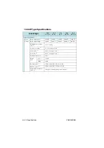
Страница 119: ...ifications This chapter contains the specifications of the unit Unless otherwise specified the specifications are based on the fol lowing conditions The load is a pure resistance After a warm up of 30 minutes with current flowing through the load ...

Страница 120: ...rent protection Protection action 3 4 Turns off the OUTPUT or POWER switch Turns on the ALM LED 8 Indicates OCP in the voltmeter 8 Preset range 10 to 110 of the rated output current Setting error Rated output current x 3 OHP Overheat protection Protection action 5 Turns off OUTPUT Turns on the ALM LED Indicates OHP in the voltmeter Display Function Voltage display Maximum display 99 99 models less...

Страница 121: ... The value inside parentheses is the variable range 3 The protection action OUTPUT off or POWER switch off is specified using BREAKER TRIP Enable Disable in CONFIG The specified protection action is common to OVP and OCP The protection action cannot be set separately for OVP and OCP The protection function recovers after correcting the abnormal condition and turning on the POWER switch 4 Protectio...

Страница 122: ...0 kΩ to 10 kΩ CV external resistance control Normal EXT R CV CONT 2 6 100 to 0 of the rated out put voltage in the range of 0 kΩ to 10 kΩ CV external resistance control Fail safe EXT V CC CONT 6 0 to 100 of the rated out put current in the range of 0 V to 10 V CC external voltage control EXT R CC CONT 1 6 0 to 100 of the rated out put current in the range of 0 kΩ to 10 kΩ CC external resistance co...

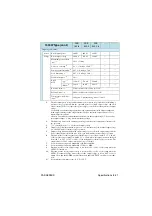
Страница 123: ...bient humidity of 70 RH or less Across the out put terminals and chassis 500 VDC 30 MΩ or more At an ambient humidity of 70 RH or less 1 J1 connector on the rear panel See the table 4 2 for the terminal arrangement 2 Photocoupler open collector output Maximum voltage 30 V maximum current sink 8 mA Insulated from the output and control circuits Status signals are not mutually insulated 3 If protect...

Страница 124: ...ctor MSTB 2 5 2 ST 5 08 1 pc Output terminal screw M8 x 16 2 sets bolts nuts and spring washers M4 x 8 2 sets Sensing terminal screw M3 x 6 2 sets Attached to the sensing connector of the unit Electromagnetic compatibility 2 3 2 Does not apply to specially ordered or modified PASs 3 Limited to products that have the CE mark on their panels Not be in compliance with EMC limits unless the ferrite co...

Страница 125: ... purpose 6 This is a Class I equipment Be sure to ground the PAS s protective conductor terminal The safety of this product is only guaranteed when the product is properly grounded 7 Pollution is addition of foreign matter solid liquid or gaseous that may produce a reduction of dielectric strength or surface resistivity Pollution Degree 2 assumes that only non conductive pollution will occur excep...

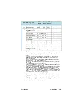
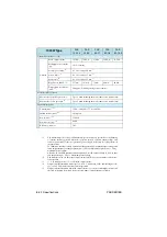
Страница 126: ... V 20 00 V 40 00 V 60 00 V 80 00 V Maximum preset voltage typ 1 105 of rating Accuracy of setting 2 0 1 of rating 10 mV 3 Source effect 4 0 05 of rating 3 mV 3 Load effect 5 0 05 of rating 5 mV 3 Transient response 6 1 ms Ripple noise p p 7 60 mV RMS 8 7 mV Rise time max 9 150 ms rated load 150 ms no load Fall time max 10 200 ms rated load 1500 ms no load Temperature coefficient max 11 100 ppm C d...

Страница 127: ...et so that rate output voltage V Set maximum preset voltage 2 The difference between the actual output voltage and the preset value under constant volt age operation 3 of rating denotes of the rated output voltage 4 Output voltage fluctuation with respect to 10 fluctuation of the nominal input voltage ex 100 VAC under constant voltage operation 5 Output voltage fluctuation when the output voltage ...

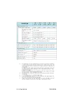
Страница 128: ...on of the nominal input volt age ex 100 VAC under constant current operation 5 Output current fluctuation when the output current is set to the rated output current and the load is changed from rated load to no load under constant current operation 350W Type PAS 10 35 PAS 20 18 PAS 40 9 PAS 60 6 PAS 80 4 5 Output Specifications cont Current Rated output current 35 00 A 18 00 A 9 000 A 6 000 A 4 50...

Страница 129: ... VAC under rated load 13 At an input voltage of 100 VAC under rated load 350W Type cont PAS 160 2 PAS 320 1 PAS 500 0 6 Output Specifications cont Current Rated output current 2 000 A 1 000 A 600 0 mA Maximum preset current typ 1 105 of rating Accuracy of setting 2 0 5 of rating 5 mA 3 Source effect 4 0 1 of rating 5 mA 3 Load effect 5 0 1 of rating 5 mA 3 Ripple noise RMS 6 5 mA Temperature coeff...

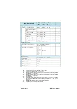
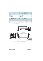
Страница 130: ...type Outline Drawing Approx 3 kg 6 61 lbs Dimensions See outline drawing 350W Type cont PAS 160 2 PAS 320 1 PAS 500 0 6 General Weight 1 Approx 3 kg 6 61 lbs Dimensions See outline drawing 4 M3s insert up to 6 mm 0 24 inch Common for rubber foot and M3 screw hole 71 2 80 MAX145 5 71 MAX25 0 98 124 4 88 MAX420 16 54 276 5 10 89 42 5 1 67 45 1 77 13 0 515 13 0 515 MAX20 0 79 ...

Страница 131: ...PAS SERIES Specifications 8 13 This page has been intentionally left blank ...

Страница 132: ... V 20 00 V 40 00 V 60 00 V 80 00 V Maximum preset voltage typ 1 105 of rating Accuracy of setting 2 0 1 of rating 10 mV 3 Source effect 4 0 05 of rating 3 mV 3 Load effect 5 0 05 of rating 5 mV 3 Transient response 6 1 ms Ripple noise p p 7 80 mV RMS 8 11 mV Rise time max 9 150 ms rated load 150 ms no load Fall time max 10 200 ms rated load 1500 ms no load Temperature coefficient max 11 100 ppm C ...

Страница 133: ...Set so that rate output voltage V Set maximum preset voltage 2 The difference between the actual output voltage and the preset value under constant volt age operation 3 of rating denotes of the rated output voltage 4 Output voltage fluctuation with respect to 10 fluctuation of the nominal input voltage ex 100 VAC under constant voltage operation 5 Output voltage fluctuation when the output voltage...

Страница 134: ...n of the nominal input volt age ex 100 VAC under constant current operation 5 Output current fluctuation when the output current is set to the rated output current and the load is changed from rated load to no load under constant current operation 700W Type PAS 10 70 PAS 20 36 PAS 40 18 PAS 60 12 PAS 80 9 Output Specifications cont Current Rated output current 70 00 A 36 00 A 18 00 A 12 00 A 9 000...

Страница 135: ... under rated load 13 At an input voltage of 100 VAC under rated load 700W Type cont PAS 160 4 PAS 320 2 PAS 500 1 2 Output Specifications cont Current Rated output current 4 000 A 2 000 A 1200 0 mA Maximum preset current typ 1 105 of rating Accuracy of setting 2 0 5 of rating 5 mA 3 Source effect 4 0 1 of rating 5 mA 3 Load effect 5 0 1 of rating 5 mA 3 Ripple noise RMS 6 10 mA 5 mA Temperature co...

Страница 136: ...11 02 lbs Dimensions See outline drawing 700W Type cont PAS 160 4 PAS 320 2 PAS 500 1 2 General Weight 1 Approx 5 kg 11 02 lbs Dimensions See outline drawing 4 M3s insert up to 6 mm 0 24 inch Common for rubber foot and M3 screw hole 62 2 44 226 8 90 MAX20 0 79 MAX420 16 54 MAX160 6 3 124 4 88 24 0 94 59 25 2 335 59 25 2 335 MAX25 0 98 42 5 1 67 142 5 5 61 112 4 41 15 25 0 6 15 25 0 6 276 5 10 89 3...

Страница 137: ...PAS SERIES Specifications 8 19 This page has been intentionally left blank ...

Страница 138: ...10 00 V 20 00 V 40 00 V 60 00 V 80 00 V Maximum preset voltage typ 1 105 of rating Accuracy of setting 2 0 1 of rating 10 mV 3 Source effect 4 0 05 of rating 3 mV 3 Load effect 5 0 05 of rating 5 mV 3 Transient response 6 1 ms Ripple noise p p 7 120 mV RMS 8 14 mV Rise time max 9 150 ms rated load 150 ms no load Fall time max 10 200 ms rated load 1500 ms no load Temperature coefficient max 11 100 ...

Страница 139: ... Set so that rate output voltage V Set maximum preset voltage 2 The difference between the actual output voltage and the preset value under constant volt age operation 3 of rating denotes of the rated output voltage 4 Output voltage fluctuation with respect to 10 fluctuation of the nominal input voltage ex 100 VAC under constant voltage operation 5 Output voltage fluctuation when the output voltag...

Страница 140: ... the nominal input volt age ex 100 VAC under constant current operation 5 Output current fluctuation when the output current is set to the rated output current and the load is changed from rated load to no load under constant current operation 1000W Type PAS 10 105 PAS 20 54 PAS 40 27 PAS 60 18 PAS 80 13 5 Output Specifications cont Current Rated output current 105 0 A 54 00 A 27 00 A 18 00 A 13 5...

Страница 141: ...er rated load 13 At an input voltage of 100 VAC under rated load 1000W Type cont PAS 160 6 PAS 320 3 PAS 500 1 8 Output Specifications cont Current Rated output current 6 000 A 3 000 A 1800 0 mA Maximum preset current typ 1 105 of rating Accuracy of setting 2 0 5 of rating 5 mA 3 Source effect 4 0 1 of rating 5 mA 3 Load effect 5 0 1 of rating 5 mA 3 Ripple noise RMS 6 15 mA 10 mA 5 mA Temperature...

Страница 142: ... 7 kg 15 43 lbs Dimensions See outline drawing 1000W Type cont PAS 160 6 PAS 320 3 PAS 500 1 8 General Weight 1 Approx 7 kg 15 43 lbs Dimensions See outline drawing 4 M3s insert up to 6 mm 0 24 inch Common for rubber foot and M3 screw hole MAX20 0 79 MAX420 16 54 MAX25 0 98 MAX160 6 3 24 0 94 95 3 74 95 3 74 124 4 88 15 25 0 61 15 25 0 61 183 5 7 22 214 8 43 42 5 1 67 276 5 10 89 350 13 78 62 2 44...

Страница 143: ...UT 6 6 Dial 6 4 Digital remote control 4 1 Display section 6 2 Dust Filter 7 2 E Exhaust port 6 6 EXT OUTPUT logic 3 9 External Contact 4 17 4 19 External Monitoring 4 21 External Resistance 4 8 4 14 External Voltage 4 5 4 11 F Factory default setting 3 2 firmware version P 2 G Grounding 1 6 I Inrush Current 2 1 Inspection 7 8 Isolation voltage 2 10 J J1 6 6 J1 Connector 4 2 L Load 2 1 Load Cable ...

Страница 144: ...ut Voltage Controlling 4 5 4 8 OVP Overvoltage Protection 3 4 Calibration 7 13 OVP OCP 6 4 P POWER 6 1 Power Turning on 3 1 Power Display 3 18 Power Supply Controller 4 1 POWER switch Protection circuit is activated 3 9 PWR ON OUTPUT 3 9 R Rack mount frame P 3 Remote Sensing 3 8 3 19 S Sensing terminal 6 6 SET 6 4 Shield 4 7 4 13 SHIFT 6 2 SHUT Shutdown 2 9 signal terminal Maximum rating 4 22 Slav...

Страница 145: ......

Страница 146: ...KIKUSUI ELECTRONICS CORP http www kikusui co jp en 1 1 3 Higashiyamata Tsuzuki ku Yokohama 224 0023 Japan Tel 81 45 593 7570 Fax 81 45 593 7571 Website ...

Отзывы: