A
Page 7 / 28
Datasheet 1.10-65.020-01-EN
RPW301-FTL
Product Description
Issue 2017-12-20 from V3.02
Installation
!
CAUTION
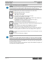
This product description contains the specific settings and functions of the en:key RPW301-FTL room
sensor. The product description of the radio partner, e.g. en:key MD10-FTL-HE valve controller
should be observed in addition to these instructions.
General installation instructions
It is not always possible to freely select the installation location of devices which communicate
wirelessly, as radio data transmission is influenced to a greater or lesser extent by structural or spatial
factors.
In order to establish operational and reliable communication paths, the following aspects must be
considered before and during planning:
!
CAUTION
Elevated humidity increases natural signal damping.
■
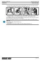
Structural factors restrict the transmission ranges which can be reached. Building materials and
screening elements (e.g. suspended ceiling elements, installation shafts, fire doors, etc.) must be
taken into consideration during planning.
NOTE
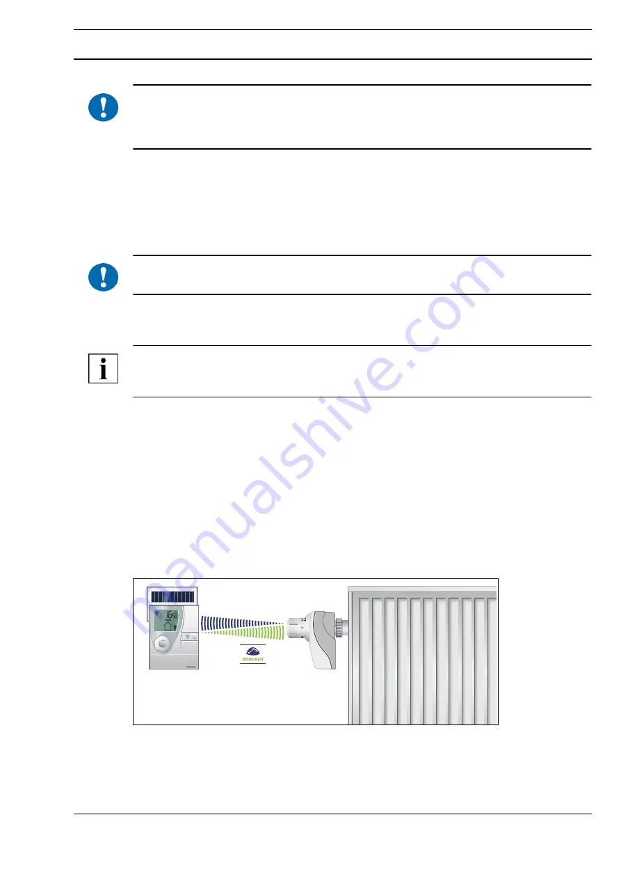
Recommendation: Plan radio paths
horizontally on a single level
with max. 30 m between the
trasmitting and receiving modules.
■
Designed only for use in rooms.
■
Observe minimum distances to potential sources of interference.
- Min. 0.5 m to high-frequency sources of interference (such as microwaves, transformers or
computers)
- Min. 0.5 m to transmitters of other radio systems (such as a cordless telephone or headphones)
- Min. 0.1 m to metal and door frames
■
Minimize the effect of wall thickness (for example partition walls or room dividers) by ensuring that
the radio signal passes through the walls at as close to a right angle as possible.
■
Do not select installation locations in the radio shadow of screening building parts/structures
No
direct reception possible.
■
Where the device is installed at the limits of reliability, change the position of the transmitter/
receiver slightly if possible (reduce overlapping effects of radio waves).

