Service Guide
5
Keysight U8001A/U8002A User’s and Service Guide
63
Constant voltage (CV) verification
Voltage programming and readback accuracy
This test is to verify that the voltage programming and readback accuracy are
within published specifications.
Procedures:
1
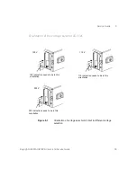
Power off the power supply and connect a DMM between the (+) and (–)
terminals of the output to be tested. Remove the electronic load or resistor
block as shown in
, to operate as an open circuit.
2
Power on the power supply.
3
When the power supply is in limit mode, program the output voltage to 0 V
and the output current to the maximum programmable value.
4
Enable the output.
5
Wait for a few seconds for the output of the power supply to settle. Make sure
that the power supply is in CV mode.
6
Record the voltage reading on the DMM (V
DMM
). This value should be within
the limit of 0 V ± 20 mV.
7
When the power supply is in meter mode, record the voltage reading displayed
on the front display of the power supply. This value should be within the limit
of V
DMM
± 20 mV.
8
Disable the output.
9
When the power supply is in limit mode, program the output voltage to full
rated value, i.e. 30 V.
10
Enable the output.
11
Wait for a few seconds for the output of the power supply to settle. Make sure
that the power supply is in CV mode.
12
Record the voltage reading on the DMM (V
DMM
). This value should be within
the limit of 30 V ± 0.125 V.
13
When the power supply is in meter mode, record the voltage reading displayed
on the front display of the power supply. This value should be within the limit
of V
DMM
± 0.125 V.
Содержание U8001A
Страница 8: ...8 Keysight U8001A U8002A User s and Service Guide THIS PAGE HAS BEEN INTENTIONALLY LEFT BLANK ...
Страница 12: ...12 Keysight U8001A U8002A User s and Service Guide THIS PAGE HAS BEEN INTENTIONALLY LEFT BLANK ...
Страница 14: ...14 Keysight U8001A U8002A User s and Service Guide THIS PAGE HAS BEEN INTENTIONALLY LEFT BLANK ...
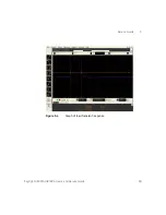
Страница 69: ...Service Guide 5 Keysight U8001A U8002A User s and Service Guide 69 Figure 5 4 Graph of load transient response ...


