


6
Setting up the W6602A Interposer
50
Keysight W6600A-series LPDDR4 BGA Interposers Installation Guide
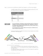
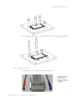
Step 2 - Making Clock Qualifier Connections
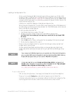
W6602A Clock Connectors
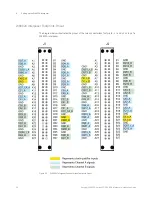
There are five clock connectors on top of a W6602A interposer namely, J3, J4, J5, J6, and J7. The
following diagram highlights these 2-pin clock connectors and also indicates what each of these pins
represents.
Figure 15
W6602A clock connectors and pins for these connectors
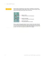
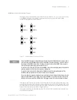
To make clock qualifier connections, you use the
Single Pin Header
s (part number - W6602-60001)
included in the W6602A shipment.
Figure 16
Single Pin Header
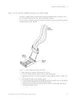
1 Solder the single pin headers into the clock connectors of the interposer from the top of the
interposer. Following are some of the recommendations for this soldering step.
• Use a soldering iron with a small tip.
• Use small diameter solder wire.
• The solder tip should touch the pad to ensure that solder wicks between the pin and pad.
Содержание LPDDR4
Страница 1: ...Keysight W6600A Series LPDDR4 BGA Interposers Installation Guide ...
Страница 4: ...4 Keysight W6600A series LPDDR4 BGA Interposers Installation Guide ...
Страница 8: ...8 Keysight W6600A series LPDDR4 BGA Interposers Installation Guide Contents ...
Страница 10: ...1 Introduction 10 Keysight W6600A series LPDDR4 BGA Interposers Installation Guide ...
Страница 78: ...Index 78 Keysight W6600A series LPDDR4 BGA Interposers Installation Guide ...
Страница 79: ...Keysight W6600A series LPDDR4 BGA Interposers Installation Guide 79 ...


