4
Interposers and Riser Soldering Guidelines
34
Keysight W6600A-series LPDDR4 BGA Interposers Installation Guide
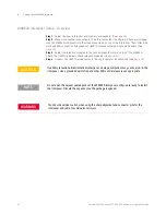
Soldering Steps
These steps and guidelines apply only to the proper method of attaching BGA interposers to their
target host boards. These do not attempt to provide instructions on how to attach BGA balls to the
interposer, nor do these attempt to suggest a flux or a solder paste process.
1 Profile Development
a
Profile must conform to the solder paste specification. Use the lowest possible temperatures
that will insure reflow.
b
Profile must also provide a slow ramp up to temperature.
c
It is recommended that the profile be developed using a non-functional sample interposer in a
location on a sample target that is similar to the actual target.
d
The highest processing temperature must be in the range of 240 °C to 260 °C. The maximum
processing time at the highest temperature must not exceed 90 seconds.
2 Material Baking
a
Prior to soldering, bake interposer (to eliminate moisture) for 2-10 hours at 250° F (121° C).
b
Shield flex areas.
c
Polyimide films absorb moisture quickly; therefore, soldering and reflow should be done within
30 minutes after baking.
d
A 7 or 9 zone conventional oven is beneficial. A conventional oven is preferred over infra-red.
e
Vacuum ovens are also used to remove water. Lower temperatures, such as 150-175 F (65-80
C) can be used. This method also reduces the oxidation of the exposed copper pads.
f
After baking, if the units are not reflowed within a few hours, these should be re-baked or
placed in a desiccant chamber.
3 Heat Shielding (applicable only to winged interposers in this series such as the W6601A
interposer).
a
Kapton tape is applied to the bottom-side covering the gold contact area and wrapping
around the outside edge to the top-side.
b
Three layers of Kapton tape are applied to the top-side covering the entire wing extending over
to the rigid board.
c
Additional insulating of the wing area is done by applying a thick coating of the high
temperature peelable masking to the Kapton tape covering the entire area to reduce the
exposure to the hot gas heat cycle.
4 Host assembly components must be shielded using Kapton tape, aluminum heat shield blanket,
or plates.
5 Site Preparation
a
If the interposer is being installed onto a new board with gold pads, these pads should be
pre-tin to ensure the pads wet properly, and to lower the chance of oxidation.
b
Add solder paste to the target board using a mini-stencil. This is recommended over using flux
only.
6 Interposer Reflow
a
Use the lowest possible temp for reflow - Use a slow ramp up to temperature.
b
Aim the shielded wings of the interposer upwards (applicable only to winged interposers in this
series such as the W6601A interposer). The minimum bend radius must be 1.27mm (0.05 In) to
insure that the copper foil does not fracture.
c
Place the interposer using vision equipped BGA placement/reflow system such as an SRT.
d
Reflow per the prepared heating profile.
7 Memory placement
a
Add staking epoxy to the four corners of the placed interposer, and cure at 150°C for 2
minutes. This time is defined from the moment the adhesive reaches the cure temperature. As
Содержание LPDDR4
Страница 1: ...Keysight W6600A Series LPDDR4 BGA Interposers Installation Guide ...
Страница 4: ...4 Keysight W6600A series LPDDR4 BGA Interposers Installation Guide ...
Страница 8: ...8 Keysight W6600A series LPDDR4 BGA Interposers Installation Guide Contents ...
Страница 10: ...1 Introduction 10 Keysight W6600A series LPDDR4 BGA Interposers Installation Guide ...
Страница 78: ...Index 78 Keysight W6600A series LPDDR4 BGA Interposers Installation Guide ...
Страница 79: ...Keysight W6600A series LPDDR4 BGA Interposers Installation Guide 79 ...


