


Keysight W6600A-series LPDDR4 BGA Interposers Installation Guide
13
Introduction to W6601A LPDDR4 BGA Interposer
2
For probing signals under 2.5Gb/s, you can use the W6601A interposer with the U4164A module’s
dual clock edge clocking and dual sample mode instead of the quad sample mode. The U4164A
module’s dual sampling with dual thresholds allows you to capture separate Read and Write samples
per clock edge.
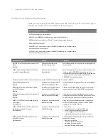
W6601A Technical Features Summary
• Probes a JEDEC LPDDR4 BGA 200 footprint. Maximum of 10 mm wide X 15 mm long LPDDR4
DRAM package can fit on top of the W6601A interposer without an additional riser or a socket to
provide clearance for the RC components.
• For the two flex wings of the interposer, the recommended bend radius is 2.5 mm (0.09") if flex is
bent at a rigid portion of the interposer.
• Logic analyzer connections are made using U4208A and U4209A ZIF probe cables. The
U4208A/U4209A ZIF connectors doors open on the top of the W6601A wings and away from
these wings.
• An isolation Tip Resistor (100 Ohms) and RC components network is present on the W6601A
interposer. No RC network present on the U4208A/U4209A probe cables. Also, there are no RCs
on the bottom of the interposer.
• Has a power plane and separate ground planes - 1.1 V (VDD2/VDDQ) and 1.8 V (VDD1).
• Also provides VDD and VDDQ power filter capacitors to allow you to make power integrity
measurements using the Keysight Power Rail probe and Infiniium S-series oscilloscope.
W6601A Riser
An LPDDR4 BGA 200 ball riser is provided with each W6601A interposer to allow the interposer to
clear surrounding devices. Optionally, you can use a Grypper socket. It is not provided with the
interposer.
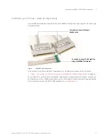
The following figure displays a riser that is provided with the W6601A interposer.
Figure 2
Riser that accompanies the W6601A interposer
To know how to solder the riser to the W6601A interposer and PC board, refer to the chapter
“W6600A-Series Interposers and Riser Soldering Guidelines"
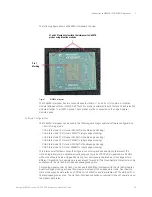
Pin 1 Marking
NOTE
The LPDDR 200 ball riser includes ground planes for optimal signal integrity. Due to these
ground planes, the riser’s alignment with the DRAM should be such that the TOP side of the
riser must point towards the DRAM and the Pin 1 indicator on the riser must orient towards the
“A1” pin of the DRAM.
Содержание LPDDR4
Страница 1: ...Keysight W6600A Series LPDDR4 BGA Interposers Installation Guide ...
Страница 4: ...4 Keysight W6600A series LPDDR4 BGA Interposers Installation Guide ...
Страница 8: ...8 Keysight W6600A series LPDDR4 BGA Interposers Installation Guide Contents ...
Страница 10: ...1 Introduction 10 Keysight W6600A series LPDDR4 BGA Interposers Installation Guide ...
Страница 78: ...Index 78 Keysight W6600A series LPDDR4 BGA Interposers Installation Guide ...
Страница 79: ...Keysight W6600A series LPDDR4 BGA Interposers Installation Guide 79 ...


