background image

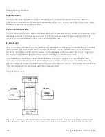
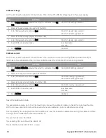
DMM measures the power supply output, and the electronic load draws current from the power supply. The
accuracy of the current monitoring resistor must be 0.01% or better, which should include any self-heating effects.

Constant Voltage (CV) verification

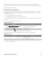
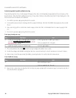
Voltage programming and readback accuracy

These tests verify that the voltage programming and the LAN or USB readback functions are within specifications.
Note that the readback values over the remote interface should be identical to those displayed on the front panel,
but with maximum resolution.

1.

Turn off the power supply using the AC line switch.

2.

Connect a DMM between the (+) and (–) terminals of the output.

3.

If you are using a computer to control the power supply, connect a LAN or USB cable from the power supply to
the PC.

4.

Turn on the power supply using the AC line switch.

Voltage programming accuracy

Step

Front Panel

SCPI

5.

Set the instrument settings as described in the test record form
under the Voltage Programming and Readback. See

Test

Record Forms

for details.

VOLT 6, (@<channel>); CURR 5, (@<channel>)

This is an example for 6 V, 5 A output.

6.

Enable the output by pressing ON key for the selected output.

OUTP ON, (@<channel>)

7.

The output status should be

CV

and the output current should be close to zero.

8.

Record the voltage measured by the DMM and verify whether it is within the limits calculated.

Voltage readback accuracy

Step

Front Panel

SCPI

9.

MEAS:VOLT? (@<channel>)

This is an example for 6 V, 5 A output.

10.

Record the voltage returned by the SCPI command query via Keysight Connection Expert, and verify whether it
is within the limits calculated.

Keysight EDU36311A Service Guide

19

Содержание EDU36311A

Страница 1: ...Service Guide EDU36311A Triple Output Programmable DC Power Supply ...

Страница 2: ...nt 10 Replacing the Battery 10 Disassembly 12 Removing the front panel 12 Removing Installing the knob 15 Installing the strap handle 15 2 Verification and Adjustments 16 Performance Verification 17 Recommended test equipment 17 Test considerations 17 Measurement techniques 18 Setup for most tests 18 Constant Voltage CV verification 19 CV load and line regulation 20 Constant Current CC verificatio...

Страница 3: ...Save the calibration data 32 Keysight EDU36311A Service Guide 3 ...

Страница 4: ...TED BY APPLICABLE LAW KEYSIGHT DISCLAIMS ALL WARRANTIES EITHER EXPRESS OR IMPLIED WITH REGARD TO THIS MANUAL AND ANY INFORMATION CONTAINED HEREIN INCLUDING BUT NOT LIMITED TO THE IMPLIED WARRANTIES OF MERCHANTABILITY AND FITNESS FOR A PARTICULAR PURPOSE KEYSIGHT SHALL NOT BE LIABLE FOR ERRORS OR FOR INCIDENTAL OR CONSEQUENTIAL DAMAGES IN CONNECTION WITH THE FURNISHING USE OR PERFORMANCE OF THIS DO...

Страница 5: ...quired from all providers of commercial computer software pursuant to the FAR and the DFARS and are set forth specifically in writing elsewhere in the EULA Keysight shall be under no obligation to update revise or otherwise modify the Software With respect to any technical data as defined by FAR 2 101 pursuant to FAR 12 211 and 27 404 2 and DFARS 227 7102 the U S government acquires no greater tha...

Страница 6: ...data Do not proceed beyond a CAUTION notice until the indicated conditions are fully understood and met A WARNING notice denotes a hazard It calls attention to an operating procedure practice or the like that if not correctly per formed or adhered to could result in personal injury or death Do not proceed beyond a WARNING notice until the indicated con ditions are fully understood and met 6 Keysig...

Страница 7: ...lace the Power Line Fuse User Replaceable Parts Battery Replacement Disassembly This chapter provides the specifications and service information on cleaning troubleshooting repair and replaceable parts of the EDU36311A This chapter also explains how to assemble and disassemble the EDU36311A Keysight EDU36311A Service Guide 7 ...

Страница 8: ...ce Center for shipping instructions including what components to ship Keysight recommends that you retain the original shipping carton for return shipments Repackaging for shipment Ensure the following to ship the unit to Keysight for service or repair Attach a tag to the unit identifying the owner and indicating the required service or repair Include the model number and full serial number Place ...

Страница 9: ...librated within the last year see Calibration Adjustment Procedures Calibration Interval for details Perform the following verifications if the unit is inoperative Verify that the ac power cord is connected to the power supply Verify that the front panel power switch is depressed Verify that the correct power line fuse is installed Refer to EDU36311A User s Guide for details Verify the power line ...

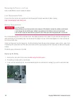
Страница 10: ...he real time clock The primary function of the clock it to provide a time stamp for the internal file system If the battery fails the clock and time stamp function will not be available No other instrument functions are affected Under normal use at room temperature the lithium battery has a life expectancy between seven and ten years Note that battery life will be reduced if the instrument is stor...

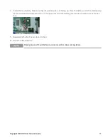
Страница 11: ...l spring see red circle below and push down on the opposite end of the battery see red arrow below to seat the bat tery 5 Reassemble the front panel when finished 6 Reset the date and time Properly dispose of the old battery in accordance with local laws and regulations Keysight EDU36311A Service Guide 11 ...

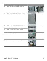
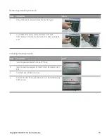
Страница 12: ...andle Then remove the plastic cap and strap handle from the instrument 2 On the bottom panel remove the rubber foot Remove four screws M4x12 with T20 Torx driver from the rubber foot Then remove the rubber foot from the instrument 3 Remove two screws M3x6 with T10 Torx driver that holds the front panel and the chassis cover 4 On the rear panel remove three screws M3x6 with T10 Torx driver 5 Pull o...

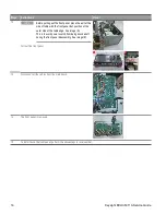
Страница 13: ...rews M3x6 from the bottom of the rear chassis 8 Remove six screws M3x6 from the metal handle support 9 Remove three screws M3x6 from the rear panel board 10 Lift up the metal handle support 11 Open the clip and remove the rear panel board from the metal handle support Keysight EDU36311A Service Guide 13 ...

Страница 14: ...side of the table edge See image A This is to avoid power switch from being knocked off during the front panel disassembly See image B Pull out the front panel 13 Disconnect all the cables from the main board 14 The front panel is removed 15 To install back the front panel perform the above steps in reverse order 14 Keysight EDU36311A Service Guide ...

Страница 15: ...ollow the shaft orientation before pushing the knob Installing the strap handle Steps Instructions Visual 1 Insert the stainless steel belt into the PVC strap 2 Insert the stainless steel gaskets to both side of the stainless steel belt 3 Cover both side with the plastic cap 4 Secure both side of the strap handle with two screws M5x10 using T25 Torx driver Keysight EDU36311A Service Guide 15 ...

Страница 16: ...nt Procedures This chapter contains the performance verification procedures which verify that the EDU36311A is operating within its published specifications This chapter also provides information on adjustments performed after a performance verification fails 16 Keysight EDU36311A Service Guide ...

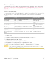
Страница 17: ...00A mainframe with N330xA modules LAN USB controller N A PC with Keysight Connection Expert loaded Oscilloscope Sensitivity 1 mV Bandwidth Limit 20 MHz Probe 1 1 with RF tip Keysight DSOX1202A oscilloscope or equivalent Terminations 1 50 Ω BNC termination 2 50 Ω 1 8 W resistor N A Variable voltage transformer or AC source Adjustable to highest rated input voltage range Power 500 VA Keysight 6813C ...

Страница 18: ... switches should be used to connect disconnect or short the load resistor For most tests an electronic load can be used The electronic load is considerably easier to use than load resistors but it may not be fast enough to test transient recovery time and may be too noisy for the noise PARD tests Fixed load resistors may be used in place of a variable load with minor changes to the test procedures...

Страница 19: ...connect a LAN or USB cable from the power supply to the PC 4 Turn on the power supply using the AC line switch Voltage programming accuracy Step Front Panel SCPI 5 Set the instrument settings as described in the test record form under the Voltage Programming and Readback See Test Record Forms for details VOLT 6 channel CURR 5 channel This is an example for 6 V 5 A output 6 Enable the output by pre...

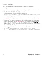
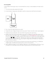
Страница 20: ... Load Regulation for details Enable the output 6 Operate the electronic load in constant current mode and set its current to the value in the test record form under CV Load Regulation See the Test Record Forms under Test Description of CV Load Regulation for details Check that the front panel CV annunciator of the power supply remains lit If it turns to CC or UR adjust the load so that the output ...

Страница 21: ... mode and set its current to the value in the test record form under CV Line Regulation See the Test Record Forms under Test Description of CV Line Regulation for details Check that the front panel CV annunciator of the power supply remains lit If it turns to CC or UR adjust the load so that the output current drops slightly until the CV annunciator lights up 8 Adjust the AC power source to low li...

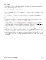
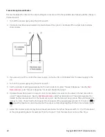
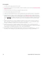
Страница 22: ... Response for details Enable the output 6 Operate the electronic load in constant current mode and set its current to the value in the test record form under Transient Response See the Test Record Forms under Test Description of Transient Response for details Set the transient level to the maximum current Set the transient duty cycle to 50 and transient fre quency to 1 kHz Check that the front pan...

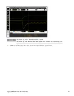
Страница 23: ...X represent t1 and t2 The oscilloscope green trace and yellow trace represent output current and output voltage trace 8 Transient response specification is met when the voltage recovers within 50 μs Keysight EDU36311A Service Guide 23 ...

Страница 24: ...programming accuracy Step Front Panel SCPI 5 Set the instrument settings as described in the test record form under Current Programming and Readback See Test Record Forms for details VOLT 6 channel CURR 5 channel This is an example for 6 V 5 A output 6 Enable the output by pressing the Output ON key OUTP ON channel 7 The output status should be CC and the output voltage should be close to zero 8 D...

Страница 25: ...record form under CC Load Regulation See the Test Record Forms under Test Descrip tion of CC Load Regulation for details Check that the front panel CC annunciator of the power supply remains lit If it turns to CV or UR adjust the load so that the output current drops slightly until the CC annunciator lights up Record the current reading Iload by dividing the voltage reading on the DMM by the resis...

Страница 26: ...y remains lit If it turns to CV or UR adjust the load so that the output current drops slightly until the CC annunciator lights up 7 Adjust the AC power source to low line voltage limit 90 VAC for nominal 100 VAC 104 VAC for nominal 115 VAC or 207 VAC for nominal 230 VAC Record the output current reading Ilowline by dividing the voltage reading on the DMM by the resistance of the current monitorin...

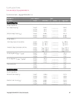
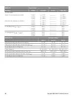
Страница 27: ... Vmax 0 025 V ______________ ______________ ______________ ______________ ______________ ______________ V0 0 005 V V0 0 01 V V0 0 01 V Vmax 0 011 V Vmax 0 025 V Vmax 0 025 V CV Load Regulation Vload Vnoload Output 1 Output 2 Output 3 2 6 mV 5 mV 5 mV ______________ ______________ ______________ 2 6 mV 5 mV 5 mV CV Line Regulation Vlowline Vhighline Output 1 Output 2 Output 3 2 6 mV 5 mV 5 mV _____...

Страница 28: ...______________ 20 mA 12 mA 12 mA CC Line Regulation Ilowline Ihighline Output 1 Output 2 Output 3 20 mA 12 mA 12 mA ______________ ______________ ______________ 20 mA 12 mA 12 mA Test Description Instrument settings Output 1 Output 2 Output 3 Voltage Programming Readback Zero Voltage V0 0 V 5 A 0 V 1 A 0 V 1 A Voltage Programming Readback Maximum Voltage Vmax 6 V 5 A 30 V 1 A 30 V 1 A CV Load Regu...

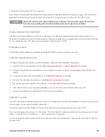
Страница 29: ...the test considerations See Performance Verification Test considerations for details 2 Perform the performance verification tests to characterize the instrument See Performance Verification for details 3 Unsecure the instrument for calibration See Calibration security for details 4 Perform the calibration procedures See Calibration procedure for details 5 Secure the instrument against the calibrat...

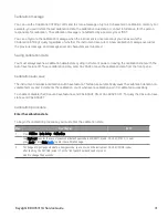
Страница 30: ...passcode you can turn on the instrument after shorting CAL SECURE jumper J1 on the front panel board as shown below and send CAL SEC CODE code to change the passcode Calibration count The instrument counts the number of times it has saved calibration data Your instrument was calibrated at the factory when you receive your instrument read and record the initial count You can only read the calibrati...

Страница 31: ... or save the calibration data from the front panel Calibration auto save The instrument includes a calibration Auto Save feature This feature automatically saves the calibration data to non volatile memory and increments the calibration count whenever a calibration point is calibrated successfully To enable or disable the CAL auto Save feature send CAL ASAVE ON or CAL ASAVE OFF To query the CAL au...

Страница 32: ...Front Panel SCPI 1 Press Perform Calibration and select the output for calibration Press Cal Curr CAL CURR LEV MIN channel 2 Measure the output current low point with the DMM 3 Enter the measured value and press Next CAL CURR reading channel CAL CURR LEV MAX channel 4 Measure the output current high point with the DMM 5 Enter the measured value and press Next CAL CURR reading channel 6 Read DONE o...

Страница 33: ...This information is subject to change without notice Keysight Technologies 2021 Edition 1 January 2021 Printed in Malaysia EDU36311 90014 www keysight com ...

Отзывы: