


Keysight Instrument Rack E7950A-1.3m E3661B-1.6m E3662B-2.0
35
4
Replace the top cap (refer to top cap replacement).
5
If appropriate, connect AC power to the cabinet.
6
Turn the main power switch ON.
Base Cover Removal
1
Remove the mounting screw located on the top edge, center, of the base
cover.
2
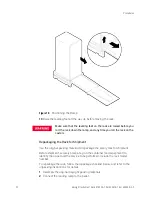
Pull the base cover away from the bottom of the rack.
Base Cover Replacement
1
Align the base cover at the bottom of the rack and roll the base cover until the
mounting holes in the rack and base cover align.
2
Insert and tighten the mounting screw.
Anti-tip Stabilizer Removal
1
Extend the anti-tip stabilizer until it stops.
2
Lift the two sidebars that go into the rack frame, and pull the stabilizer away
from the rack.
Anti-tip Stabilizer Replacement
1
Align the two extension arms with the opening at the bottom of the rack, and
insert the arms at an angle. This allows the stop tabs to go into the rack
cavity for the stabilizer.
2
Push the anti-tip stabilizer all the way into the rack.
Rear Door Hinge Removal
1
Remove the rear door (refer to Rear Door Removal).
2
Remove the two mounting screws from the rack column (on the upper hinge,
also remove the two mounting screws in the side panel), and lift the door
hinge away.
Connections from the PDU front panel switch harness and the
switch in the forehead must be made correctly to ensure normal
PDU operation. Failure to do so can result in PDU failure or
inconsistent PDU operation
.