Preparing for Imaging
5
Keysight 5500 SPM User’s Guide
5-8
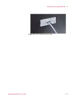
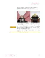
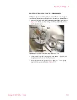
Figure 4-8
Holding the tweezers as shown, remove a probe from the
protective case
5
With the free hand, use the spring key to rock back the retainer
spring (
), pulling it back until it contacts the scanner body.
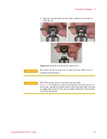
6
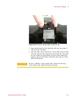
Place the probe between the guides such that a little more than half
of the probe extends over the lens (placement will vary depending on
the type and shape of the probe).
shows this process. The
final probe position should be as shown in
Figure 4-9
Hold back the retaining spring while placing the probe
7
Gently lower the spring clip to hold the probe in place.
Содержание 5500
Страница 1: ...Keysight 5500 Scanning Probe Microscope User s Guide ...
Страница 2: ......
Страница 9: ...Read This First N9410 90001 Keysight 5500 SPM User s Guide ix Declaration of Conformity ...
Страница 174: ...Additional Imaging Modes 5 Keysight 5500 SPM User s Guide 5 40 Figure 7 23 Plug in Images window ...
Страница 215: ...Closed Loop Scanners 5 Keysight 5500 SPM User s Guide 5 17 Save the calibration file X Y Z calibration is now complete ...
Страница 274: ...Temperature Control 5 Keysight 5500 SPM User s Guide 5 8 Figure 13 10 7500 9500 hot sample plate wiring diagram ...
Страница 275: ...Temperature Control 5 Keysight 5500 SPM User s Guide 5 9 Figure 13 11 5500 hot MAC sample plate wiring diagram ...
Страница 276: ...Temperature Control 5 Keysight 5500 SPM User s Guide 5 10 Figure 13 12 7500 9500 hot MAC sample plate wiring diagram ...
Страница 284: ...Temperature Control 5 Keysight 5500 SPM User s Guide 5 18 Figure 13 21 5500 Peltier Cold sample plate wiring diagram ...
Страница 297: ...Thermal K 5 Keysight 5500 SPM User s Guide 5 9 Figure 14 8 Select units after calibrating the Force Constant ...
Страница 330: ...Keysight Technologies 5500 SPM User s Guide Part Number N9410 90001 Revision H Keysight Technologies 2015 ...


