Additional Imaging Modes
5
Keysight 5500 SPM User’s Guide
5-3
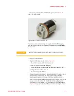
located beneath the tip, can be field-replaced to adjust the sensitivity if
necessary.
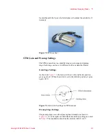
Figure 7-2
STM scanner
STM Gain and Preamp Settings
The STM scanner has two amplifier stages: gain stage and preamp
stage. Each stage can be set to different values as described below.
Gain Stage Settings
As shown in
, the Gain switch set to the right side position
gives a gain of 1. When the switch is set to the left side position, it gives
a gain of 10.
Figure 7-3
Gain switch settings for STM scanner
Preamp Stage Settings
The preamp stage uses a fixed preamp board module as shown in
. It can be replaced with different sensitivity settings as noted
in
. The standard scanner has the module with 10 nA/V
Содержание 5500
Страница 1: ...Keysight 5500 Scanning Probe Microscope User s Guide ...
Страница 2: ......
Страница 9: ...Read This First N9410 90001 Keysight 5500 SPM User s Guide ix Declaration of Conformity ...
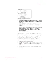
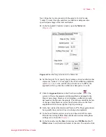
Страница 174: ...Additional Imaging Modes 5 Keysight 5500 SPM User s Guide 5 40 Figure 7 23 Plug in Images window ...
Страница 215: ...Closed Loop Scanners 5 Keysight 5500 SPM User s Guide 5 17 Save the calibration file X Y Z calibration is now complete ...
Страница 274: ...Temperature Control 5 Keysight 5500 SPM User s Guide 5 8 Figure 13 10 7500 9500 hot sample plate wiring diagram ...
Страница 275: ...Temperature Control 5 Keysight 5500 SPM User s Guide 5 9 Figure 13 11 5500 hot MAC sample plate wiring diagram ...
Страница 276: ...Temperature Control 5 Keysight 5500 SPM User s Guide 5 10 Figure 13 12 7500 9500 hot MAC sample plate wiring diagram ...
Страница 284: ...Temperature Control 5 Keysight 5500 SPM User s Guide 5 18 Figure 13 21 5500 Peltier Cold sample plate wiring diagram ...
Страница 297: ...Thermal K 5 Keysight 5500 SPM User s Guide 5 9 Figure 14 8 Select units after calibrating the Force Constant ...
Страница 330: ...Keysight Technologies 5500 SPM User s Guide Part Number N9410 90001 Revision H Keysight Technologies 2015 ...

