Figure
8
14
-
Port System Locking Feet
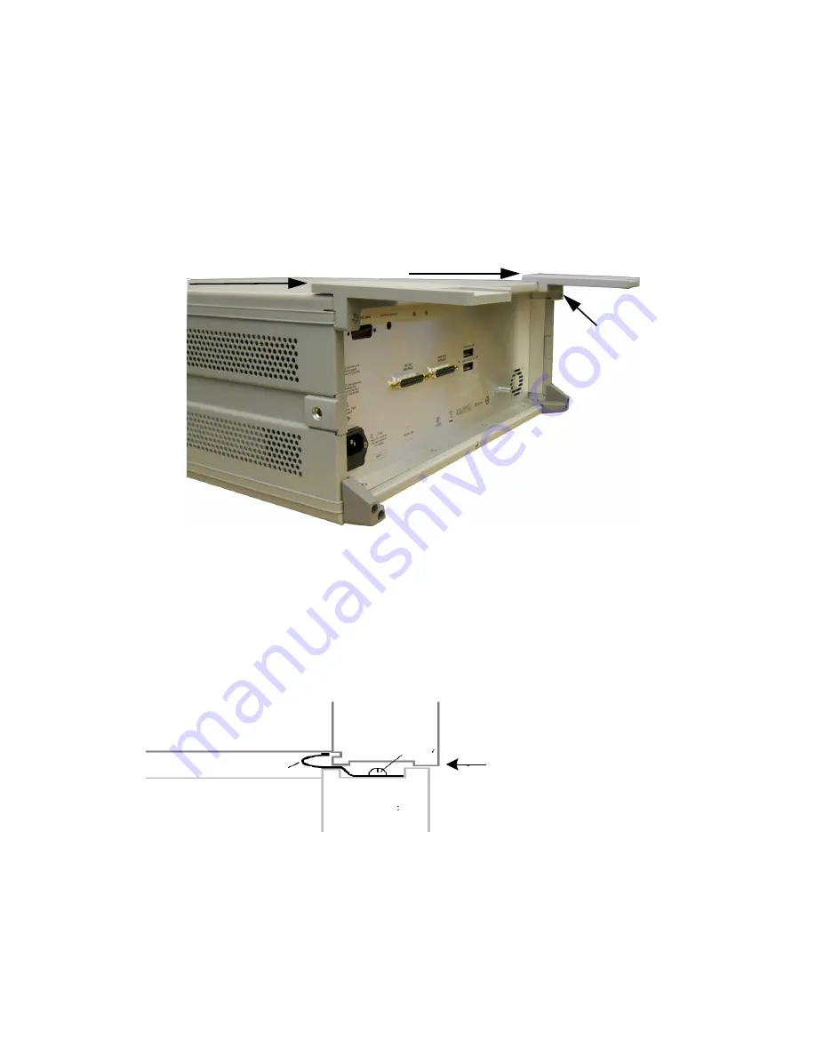
6. Place the network analyzer on top of the Test Set and ensure that the front frame of the
network analyzer is positioned slightly forward of the Lock-Links that are attached to the
Test Set. Slide the network analyzer back so the locks engage the front frame of the analyzer.
Figure
9
Locking the Analyzer to the Test Set
N5242-20138
N5242-20139
Test Set
Front Frame
Network Analyzer
Front Frame
Slide the network
a
nalyzer
back to engage the
L
ock
-Link
in the back of the network
analyzer's front frame
Lock
-
Link
screw
4. Remove the two upper standoffs from the Test Set, using the T20 Torx driver.
5. Install the two rear locking feet onto the U3024AH10. Looking at the front panel, the
N5242-20138 is the right foot and the N5242-20139 is the left foot. Use the two screws
that are included with this option.
Screw, 0515-2317
T15 M3.5 x 0.6 12mm
Keysight U3024AH10 User's and Service Guide
16
Содержание U3024AH10
Страница 5: ...U3024AH10...
Страница 31: ...Figure 17 24 Port RF Interface Cable Configuration Keysight U3024AH10 User s and Service Guide 26...
Страница 52: ...Figure 38 Example 1 Test Set Signal Path 47 Keysight U3024AH10 User s and Service Guide...
Страница 81: ...System Block Diagrams Figure 56 14 Port System Configuration Keysight U3024AH10 User s and Service Guide 76...
Страница 82: ...Figure 57 24 Port System Configuration 77 Keysight U3024AH10 User s and Service Guide...
Страница 83: ...Figure 58 2 Way High Power Configuration 1 Watt Keysight U3024AH10 User s and Service Guide 78...
Страница 84: ...Figure 59 Odd Port High Power Configuration 1 Watt 79 Keysight U3024AH10 User s and Service Guide...
Страница 85: ...Figure 60 Port 1 High Power Configuration 1 Watt Keysight U3024AH10 User s and Service Guide 80...
Страница 95: ...Servicing Diagram Figure 67 Test Set Electrical Diagram Keysight U3024AH10 User s and Service Guide 90...
Страница 105: ......


