


4 Disassembly
48
Series E4360 Service Guide
Installing a Redundant Ground for 400 Hz Operation
Operation at 400 Hz requires the installation of a redundant ground from
the instrument chassis to earth ground. The redundant ground must be
permanently attached to the unit as well as to the earth ground point.
The following procedure only describes how to make the permanent
connection at the unit. The user must ensure the integrity and
permanence of the connection at the earth ground point.
The following customer-supplied hardware is required:
Ground wire (14/16 AWG)
Uninsulated ring terminal for attaching wire to unit
(Tyco p/n 34124 or equivalent)
Hardware for attaching wire to earth ground point
The following tools are required to install the redundant ground:
3/8 inch hex wrench
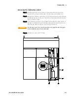
Step 1. Remove the top cover of the interface board as previously described
under “Accessing the Calibration switch”.
Step 2. Use the wrench and remove the binding post (1) from the rear of the
chassis. The binding post is located between the AC input connector and
the GPIB connector.
Step 3. Crimp the appropriate ring terminal (2) onto the end of the ground wire.
Step 4. Place the ring terminal onto the threaded end of the binding post. Re-
install the binding post on the chassis with the washer and nut (3).
Step 5. Rotate the ring terminal so that the ground wire does not interfere with
any other connectors on the back of the unit. Use the wrench and
tighten the binding post to the chassis (Torque = 20 – 25 in-lb.).
1
2
3
1
2
3
Содержание E4360 Series
Страница 1: ...Service Guide Keysight Technologies Series E4360 Modular Solar Array Simulator ...
Страница 2: ......
Страница 6: ......
Страница 10: ......
Страница 40: ......
Страница 44: ...4 Disassembly 44 Series E4360 Service Guide ...
Страница 64: ......
Страница 72: ......