background image

Safety and Regulatory Information

This procedure requires the user to send SCPI commands to the instrument. Connect to
the instrument via LAN or USB. Use the Keysight IO Libraries to send SCPI commands.

General Information

The equipment is for industrial use.

Equipment operators are subject to all applicable safety regulations. Along with the warning and
safety notices in this manual, all relevant safety, accident prevention, and environmental regulations
must also be followed. In particular, the operators of the equipment:

l

Must be informed of the relevant safety requirements.

l

Must have read and understood the operating manual before using the equipment.

l

Must use the designated and recommended safety equipment.

The following general safety precautions must be observed during all phases of operation of this
instrument. Failure to comply with these precautions or with specific warnings or instructions
elsewhere in this manual violates safety standards of design, manufacture, and intended use of the
instrument. Keysight Technologies assumes no liability of the customer’s failure to comply with the
requirements.

Safety Warnings

A WARNING notice denotes a hazard. It calls attention to an operating procedure, practice, or the like
that, if not correctly performed or adhered to, could result in personal injury or death. Do not proceed
beyond a WARNING notice until the indicated conditions are fully understood and met.

Should network communication issues occur, the instrument settings shown in the
Browser Web Control page may not represent the actual state of the instrument. This may
result in unexpected hazardous voltages on the output and sense connections that could
result in personal injury, death, or damage to a device under test. Before touching the out-
put or sense connections or connecting to a device under test, always verify the state of
the instrument.

Product Grounding

The instrument is a Class 1 product and is provided with a grounding-type power cord set.
The instrument chassis and cover are connected to the instrument electrical ground to
minimize shock hazard. The ground pin of the cord set plug must be firmly connected to
the electrical ground (safety ground) terminal at the power outlet. Any interruption of the
protective earth (grounding) conductor or disconnection of the protective earth terminal
will cause a potential shock hazard that could result in personal injury or death.

Safety and Regulatory Information

6

Keysight AC6800B Series Operating and Service Guide

Содержание AC6801B

Страница 1: ...Operating and Service Guide Keysight AC6800B Series Basic AC Sources...

Страница 2: ...Use 14 Introduction to the Instrument 19 Instrument Ratings 23 Installing an Optional Interface Board 24 Rack Mounting 25 Connecting the Power Cord 28 Switchboard and Circuit Breaker Requirements 32...

Страница 3: ...15 CALibrate Subsystem 116 CURRent Subsytem 121 DISPlay Subsystem 123 FETCh and MEASure Subsystems 125 FREQuency Subsystem 130 HCOPy Subsystem 132 IEEE 488 Common Commands 133 INITiate Subsystem 139 L...

Страница 4: ...CLUDING BUT NOT LIMITED TO THE IMPLIED WARRANTIES OF MERCHANTABILITY AND FITNESS FOR A PARTICULAR PURPOSE KEYSIGHT SHALL NOT BE LIABLE FOR ERRORS OR FOR INCIDENTAL OR CONSEQUENTIAL DAMAGES IN CONNECTI...

Страница 5: ...computer software or commercial computer software documentation that is not customarily provided to the public or 2 Relinquish to or otherwise provide the government rights in excess of these rights c...

Страница 6: ...ce denotes a hazard It calls attention to an operating procedure practice or the like that if not correctly performed or adhered to could result in personal injury or death Do not proceed beyond a WAR...

Страница 7: ...se Use indoors only Do not operate the instrument near flammable gases or fumes To prevent the possibility of explosion or fire do not use the product near alcohol thinner or other combustible materia...

Страница 8: ...ood earth ground This product is an IEC Safety Class I equipment equipment with a protective conductor terminal Be sure to ground earth the unit Connect the protective conductor terminal to earth grou...

Страница 9: ...connections to the unit before applying power Note the instrument s external markings described under Safety Symbols You cannot use standard rack mounting support rails as they would block the airflow...

Страница 10: ...t may malfunction Do not install the product on an inclined surface or location subject to vibrations The product may fall or tip over causing damage or injuries or both Operational Cautions You canno...

Страница 11: ...ance with the Canadian Inter ference Causing Equipment Standard The C tick mark is a registered trademark of the Spectrum Man agement Agency of Australia This signifies compliance with the Aus tralian...

Страница 12: ...umentation product Do not dispose in domestic household waste To return unwanted products contact your local Keysight office or see about keysight com en companyinfo environment takeback shtml for mor...

Страница 13: ...the Instrument Instrument Ratings Installing an Optional Interface Board Rack Mounting Connecting the Power Cord Switchboard and Circuit Breaker Requirements Quick Start Interface Connections Remote...

Страница 14: ...tion booklet Certificate Of Calibration and envelope Refer to the box contents list for any additional items that may be included with your shipment If anything is missing please contact your nearest...

Страница 15: ...torage 10 to 60 C 14 to 140 F 90 or less relative humidity noncondensing Altitude Up to 2000 m Provide Adequate Air Flow Do not block the air intake at the front of the instrument or the exhaust at th...

Страница 16: ...AC6802B 1 Getting Started 16 Keysight AC6800B Series Operating and Service Guide...

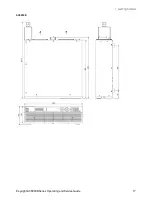
Страница 17: ...AC6803B Keysight AC6800B Series Operating and Service Guide 17 1 Getting Started...

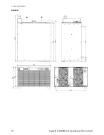
Страница 18: ...AC6804B 1 Getting Started 18 Keysight AC6800B Series Operating and Service Guide...

Страница 19: ...The indicator next to this switch shows the display status Green indicates normal operation Yellow indicates that the display is in screen saver mode or that the instrument is in the boot up pro cess...

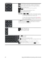
Страница 20: ...ly send the SYSTem ERRor query The SCPI Status Byte and Standard Event Registers provide an overview of error conditions The puqt arrows move around the command menus and select characters in alphanum...

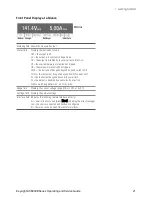
Страница 21: ...nt has gone beyond its RMS current limit PL the instrument has gone beyond its power limit SF the output is disabled by a sense fault protection WDG watchdog protection no I O activity Range field Dis...

Страница 22: ...cord ground must not be defeated If only a two contact electrical outlet is available connect the instrument s chassis ground screw see above to a good earth ground AC6801B AC6802B AC6803B AC6804B 1 G...

Страница 23: ...s 6400 VA or less Power factor 0 9 typical Maximum input current 8 A 4A 100V 200V 6 7A 3 5A 120V 230V 16 A 8A 100V 200V 13 4 A 7 0 A 120 230V 32A 16A 100V 200V 26 8 A 14 0 A 120 230V 64 A 32A 100V 200...

Страница 24: ...switch is turned off 2 Touch the grounded metal to discharge your static electricity 3 Unscrew the slot cover screws and remove the cover Retain the cover for use in case the interface board is ever...

Страница 25: ...iption Quantity 1 Bracket 2 2 Flat Head Screws M4 0 7 10 4 3 Clip Nuts for Rack Frame 10 32 0 5 in 4 4 Dress Screws with Nylon Washer Phantom Gray 4 Rack Mounting Kit AC68BRAC6 for AC6804B Item Descri...

Страница 26: ...e feet from the bottom panel Using the accompanying M4 10 flat head screws install the brack ets Using the accompanying dress screws and clip nuts 10 32 mount the instrument in the rack 1 Getting Star...

Страница 27: ...m the bottom panel Using the accompanying M4 10 flat head screws install the brackets Using the accompanying dress screws and clip nuts 10 32 mount the instrument in the rack Keysight AC6800B Series O...

Страница 28: ...cord to connect to the AC line If the supplied power cord cannot be used due to the rated voltage or the plug shape have a qualified engineer replace it with an appropriate power cord of length 3 m or...

Страница 29: ...oard circuit breaker before connecting the cord Do not use the terminal block with the terminal cover removed Possible Fire Have a qualified engineer connect the power cord to the switchboard Make sur...

Страница 30: ...h terminal ground requires an extra length of wire compared to the Line and Neutral wires Always connect the ground wire first 5 Install the terminal cover over the terminal block AC6802B Place the co...

Страница 31: ...inals For termination attach a crimp style terminal to each wire that meets the terminal screws of the switchboard to be connected and then securely connect the wires to the terminal screws Connection...

Страница 32: ...rcuit breaker requirements Rated current AC6802B 20 A AC6803B 40 A AC6804B 80 A Dedicate the circuit breaker for the AC6802B AC6803B and AC6804B Keep the switchboard easily accessible at all times App...

Страница 33: ...s guidance for circuit breaker sizing for various nominal mains voltages The guidance for North American mains voltages 120 208 and 240 V includes the 1 25 factor associated with the 80 rule Guidance...

Страница 34: ...15 15 20 40 IEC 60898 1 and European Standard EN 60898 1 Standard Sizes 6 10 13 16 20 25 32 40 50 63 80 and 100 A NEMA Standard Sizes also commonly used in Japan 15 20 25 30 35 40 45 50 60 70 80 90 an...

Страница 35: ...s An automatic power on self test ensures that the instrument is operational It takes about 10 seconds for the instrument to initialize before it is ready for use If the instrument does not turn on ve...

Страница 36: ...iew Enter Numeric and Alphanumeric Values When the focus is on a text box its label is highlighted within a dashed outline and its present value is displayed in white text on a dark background Pressin...

Страница 37: ...mode Set the Output Current Limit To limit the output current press Menu Output Current Use the Select key to enable or disable latching Specify the AC and DC current limits and press Enter to save yo...

Страница 38: ...et help pertaining to those particular settings Press any key other than a navigation arrow to exit Help View the help information for displayed messages Whenever a limit is exceeded or any other inva...

Страница 39: ...utility of the Keysight IO Libraries Suite running the computer will auto matically recognize the instrument This may take several seconds When the instrument is recog nized your computer will display...

Страница 40: ...ru ment If the instrument cannot be found add the instrument using its host name or IP address 3 You can now use Interactive IO within the Connection Expert to communicate with your instrument or you...

Страница 41: ...it when the instrument is disconnected and then reconnected to a network The instrument ships with an Automation Ready CD that contains Keysight IO Libraries Suite software which must be installed to...

Страница 42: ...onfiguration The GPIB interface requires the optional GPIB interface board and uses a standard IEEE 488 cable to connect to the computer Each device on the GPIB IEEE 488 interface must have a unique w...

Страница 43: ...r assigning dynamic IP addresses to networked devices With dynamic addressing a device can have a different IP address every time it connects to the network Viewing Active Settings To view the current...

Страница 44: ...ront Panel SCPI Command Menu System IO LAN Reset or Menu System IO LAN Defaults Select Reset to activate the selected LAN settings and restart networking Not available Modifying the LAN Settings Press...

Страница 45: ...A value of 0 0 0 0 indicates that no default gateway is defined Dot notation addresses nnn nnn nnn nnn where nnn is a value from 0 to 255 must be expressed with care as most PC web software interprets...

Страница 46: ...t server is defined Dot notation addresses nnn nnn nnn nnn where nnn is a value from 0 to 255 must be expressed with care as most PC web software interprets byte values with leading zeros as octal bas...

Страница 47: ...ble Web control using the Web page Browser Web Control tab Using the Web Interface Your instrument has a built in Web interface that lets you control it directly from the Web browser on your computer...

Страница 48: ...puter s Web browser 2 Enter the instrument s host name or IP address into the browser s Address field The following wel come page will appear 1 Getting Started 48 Keysight AC6800B Series Operating and...

Страница 49: ...s voltages on the output and sense connections that could result in personal injury death or damage to a device under test Before touching the output or sense connections or connecting to a device und...

Страница 50: ...he data socket which uses a fixed port number the port number for a control socket varies and must be obtained by sending the following SCPI query to the data socket SYSTem COMMunicate TCPip CONTrol A...

Страница 51: ...0 5 26 49 8 8 8 37 61 14 5 13 3 88 The values vary depending conditions such as the wire covering insulator and material allowable temperature and whether they are multi core cables For cables other t...

Страница 52: ...residual voltage still remains at the output terminals Do not touch the output terminal block for at least 20 seconds after the power switch is tuned off There is a danger of electric shock Do not use...

Страница 53: ...G terminal of the instrument s OUTPUT terminal block Be sure to use a wire that is greater than or equal to the diameter of the wires used to connect the load 4 Attach the terminal cover that you rem...

Страница 54: ...the switch circuit use a two pole type switch that cuts off L and N wires simultaneously The current rating of the switch must be greater than or equal to the instrument s maximum current Possible ele...

Страница 55: ...se pug from the rear panel 3 Make your connections as shown in the following figure Connect the Ls line sense wire to pin 3 Con nect the Ns neutral sense wire to pin 1 Sense wires size should be from...

Страница 56: ...volts l When the sense wires come loose open during operation The following sense faults will trigger a sense fault protection SF on the front panel and disable the output l When the sense wiring is...

Страница 57: ...cified voltage As it does so if the output is on the instrument turns the output off for approximately 0 5 seconds and turns it on again after the range switches The tables below indicate the output v...

Страница 58: ...hat the upper limit is greater than or equal to the lower limit Output mode Voltage Range Lower Limit Upper Limit AC Mode 155 V 0 0 to 157 5 V 0 0 to 315 0 V 310 V 0 0 to 315 0 V 0 0 to 315 0 V DC mod...

Страница 59: ...ngs are not checked for errors in response to range changes If these settings will become active due to output mode changes such as switching coupling from AC to DC or due to the enabling of soft limi...

Страница 60: ...ult of the output coupling change 6 Settings that are valid on the low output range are always valid on the high output range but the Range Error Checking and Soft Limits Checking are both performed w...

Страница 61: ...h active parameter setting For AC DC mode the peak value 2 AC DC cannot exceed 389 V For AC mode the voltage setting must be from 0 to the full scale value of the range and for DC mode the value must...

Страница 62: ......

Страница 63: ...t Mode Specifying Output Coupling Programming AC Output Programming DC Voltage Setting Limit Values Turning the Output On and Off Storing and Retrieving Instrument States Configuring Instrument Prefer...

Страница 64: ...are Models and Options The AC6800B Series includes four models and four options as shown below Model Maximum Power VA AC6801B 500 AC6802B 1 000 AC6803B 2 000 AC6804B 4 000 The AC6800B Series has four...

Страница 65: ...e or technical support contact Keysight Technologies Contacting Keysight Technologies United States 800 829 4444 Europe 31 20 547 2111 Japan 0120 421 345 Use www keysight com find assist to contact Ke...

Страница 66: ...ects voltage range Coupling Selects output coupling Current Sets output current limits Phase Sets output on phase Measure IpkHold Displays or clears peak held current Coupling Selects the measurement...

Страница 67: ...commands Display Configures screen saver and start up meter view Saver Configures the screen saver View Configures the start up meter view Lock Unlock Locks the front panel keys with a password Admin...

Страница 68: ...R_ VIP and METER_ALL Menu Toggles between the top Menu level and the Metering Mode display METER_VI METER_VIP or METER_ALL Protect Opens the Protect menu equivalent to Menu Protect Back Backs out of c...

Страница 69: ...ecrement a Settings field No effect on numbers entered under the Menu key Enter Finishes a numeric entry You can immediately change values by directly entering numbers into the Settings field Display...

Страница 70: ...nge up to 155 VAC 219 VDC HIGH Selected range up to 310 VAC 438 VDC AUTO Autoranging selected not available in EXT AC or EXT DC mode Interface Err One or more messages in error queue LAN displayed LXI...

Страница 71: ...or voltage and frequency are disabled You cannot set the voltage limit when the instrument is being controlled by external analog signals An excessive external voltage may damage the load Front Panel...

Страница 72: ...AC DC mode the combined peak voltage must be between 222 5 and 222 5 V for the low range or 445 and 445 V for the high range Turn the output off to change the output coupling The instrument performs...

Страница 73: ...range Output Mode Front Panel Menu Output Voltage AC SCPI OUTPut COUPling AC Voltage Range Front Panel Menu Output Range SCPI SOURce VOLTage RANGe UPPer 155 310 MINimum MAXimum The output must be off...

Страница 74: ...re safety functions that prevent unintentional settings For example setting the voltage Lo Limit and Hi Limit to 10 and 20 Vrms would prevent you from specifying 175 Vrms when you intended 17 5 Vrms U...

Страница 75: ...ect DONE To specify the frequency limits check the Enable Limits box to enable the Lo Limit and Hi Limit The frequency limits do not limit output they prevent unintentional settings For example settin...

Страница 76: ...e VOLTage 110 Specify 110 V FREQuency 55 Specify 55 Hz OUTPut ON Turn the output on When the output is turned on you cannot change the output mode or voltage range You must turn the output off first H...

Страница 77: ...minimum 40 Hz FREQuency 70 Sets frequency to 70 Hz The commands above set the limits to accommodate the widest possible VOLTage and FREQuency settings within the given range On the 155 V voltage range...

Страница 78: ...Voltage DC VOLTage OFFSet LIMit 5 Specify the DC voltage to be output VOLTage OFFSet 6 Turn the output on On Off OUTPut ON 1The DC voltage range for the 155 V range is 222 5 V and for the 310 V range...

Страница 79: ...s average DC current or RMS AC current that exceeds the limit it displays OC in the Status field and sets the CL RMS bit bit 12 in the STATus QUEStionable register If the instrument detects peak curre...

Страница 80: ...AC6802B AC6803B AC6804B AC Mode 0 1 to 5 25 A 0 2 to 10 5 A 0 4 to 21 0 A 0 8 to 42 0 A DC mode 0 1 to 4 2 A 0 2 to 8 4 A 0 4 to 16 8 A 0 8 to 33 6 A 2 User Information 80 Keysight AC6800B Series Ope...

Страница 81: ...il the load energy is discharged The discharge time of the internal capacitor when no load is connected is approximately 0 1 seconds To prevent the possibility of electric shock do not touch the outpu...

Страница 82: ...its lower and upper DC Voltage limits lower and upper Current limit Current limit operation Save and Recall Instrument States You can save instrument states into 10 nonvolatile state storage locations...

Страница 83: ...power on state Reset state RST is the factory default Recall state 0 will recall the state saved in location 0 Auto resume causes the unit to power up in its power down state State changes occurring...

Страница 84: ...n I O restores the display whenever any I O interface activity occurs SCPI SYSTem SSAVer STATe SYSTem SSAVer DELay SYSTem SSAVer RWAKeup Specify the Startup Meter View 1 Press Menu System Preferences...

Страница 85: ...l There is no factory default password The password must be 4 to 15 characters long and may include any of these characters Characters Description A Z Upper case letters a z Lower case letters 0 9 Num...

Страница 86: ...d measurement low and high ranges Current Calibrate current measurement low and high ranges Count View the calibration count The calibration count is incremented whenever calibration is saved the admi...

Страница 87: ...tection fault If this box is not checked a current limiting event will decrease the output voltage until the current goes below the limit Current limit settings vary by model as shown below The AC lim...

Страница 88: ...received within the specified delay period which may be set between 1 and 3600 seconds factory default 60 Press Menu Protect WDog to configure watchdog protection It is disabled by factory default SC...

Страница 89: ...ent PEAK HOLD CLEar Configure Measurement Coupling Press Menu Measure Coupling to configure measurement coupling AC DC or AC DC The factory default is AC DC AC DCThe RMS value of the output is present...

Страница 90: ...voltage limit when the AC source is being controlled using external analog signals Accidentally applying an excessive external voltage may damage the load Analog controls Control Description INPUT BNC...

Страница 91: ...INPUT terminal Step 4 Turn the AC source on Step 5 Select EXT_AC mode Step 6 Select a voltage range 155 V or 310 V Autoranging is not available in analog mode If Auto was selected before the instrumen...

Страница 92: ...when 310 V range is selected with respect to a signal input ranging from 10 V to 10 V Step 1 Turn the AC source off Step 2 Set the ATT switch On or Off Off The input voltage range is 1 90 V to 1 90 V...

Страница 93: ...t so that the output voltage is as close to 0 V DC as possible with the ATT switch turned off and the input BNC connector shorted Adjusting the Gain You can fine adjust the gain by turning the GAIN ad...

Страница 94: ...stored and retrieved on a first in first out basis Once an error has been read either by remote command or from the front panel it is cleared The only exception is self test errors which cannot be cle...

Страница 95: ...by Subystem ABORt Subsystem CALibrate Subsystem CURRent Subsystem DISPlay Subsystem FETCh MEASure Subsystem FREQuency Subsystem HCOPy Subsystem IEEE 488 Common Commands INITiate Subsystem LXI Subsyste...

Страница 96: ...IEEE 488 2 standard defines common commands that perform functions such as reset self test and status operations Common commands always begin with an asterisk are three characters long and may includ...

Страница 97: ...before the parameters Insert a space between the question mark and the first parameter You can query the value of most parameters For example to query the output voltage send VOLTage You can also que...

Страница 98: ...or example you could send DISPlay WINDow TEXT Test in progress A vertical bar separates multiple parameter choices for a given command string For example AC DC ACDC in the OUTPut COUPling command indi...

Страница 99: ...specify settings that have a limited number of values like IMMediate EXTernal or BUS Like command keywords they may have short and long forms You can mix upper and lower case letters Query responses a...

Страница 100: ...eared The instrument is prepared to accept a new command string The ABORt command is the recommended method to terminate an instrument operation Typical Command Processing Times The table below docume...

Страница 101: ...cription of the individual registers and register groups The status diagram below provides an graphical view of how the status registers and groups are interconnected Keysight AC6800B Series Operating...

Страница 102: ...is read Reading the Event register clears it The EVENt register bits are automatically set according to the changes in the CONDition register and is reset when read The rule varies depending on the p...

Страница 103: ...ionable Status group are logically OR ed into the QUEStionable summary bit 3 of the Status Byte register See Status Registers for a description of each register Bit Value Bit Name Description 0 1 OV O...

Страница 104: ...it Name Description 0 1 Operation Com plete OPC All commands before and including OPC have completed 1 2 not used 0 is returned 2 4 Query Error QYE The instrument tried to read an empty output buffer...

Страница 105: ...R An event in the Operation Status register has been generated Bits must be enabled see STATus OPERation ENABle Master Status Summary and Request for Service Bits MSS is a real time unlatched summary...

Страница 106: ...brate SAVE Saves the calibration data and date not the administration password into nonvolatile memory CALibrate STATe ON 1 OFF 0 pass word CALibrate STATe Enables or disables calibration mode CALibra...

Страница 107: ...STATe Turns the front panel display on or off DISPlay WINDow TEXT string DISPlay WINDow TEXT Displays a text message on the display DISPlay WINDow TEXT CLEar Clears the text message from the display...

Страница 108: ...MEASure POWer DC Average DC power W FETCh POWer AC REAL MEASure POWer AC REAL AC active power W FETCh POWer AC APParent MEASure POWer AC APParent AC apparent power VA FETCh POWer AC PFACtor MEASure PO...

Страница 109: ...e MINimum MAXimum SOURce FREQuency LIMit UPPer MINimum MAXimum Sets the lower or upper AC frequency soft limit SOURce FREQuency LIMit STATe ON 1 OFF 0 SOURce FREQuency LIMit STATe Enables or disables...

Страница 110: ...memory location SRE value SRE Service request enable command and query STB Status byte query Reads the Status Byte Register which contains the status summary bits and the Output Queue MAV bit TRG Trig...

Страница 111: ...tection OUTPut PROTection WDOG STATe ON 1 OFF 0 OUTPut PROTection WDOG STATe Enables or disables the I O watchdog timer OUTPut PROTection WDOG DELay value MINimum MAXimum OUTPut PROTection WDOG DELay...

Страница 112: ...PRESet Initializes the transition and enable filters for both SCPI register groups OPERation and QUEStionable STATus QUEStionable EVENt Queries the event register for the Questionable Status group ST...

Страница 113: ...Ver DELay MINimum MAXimum Sets the delay time for screen saver activation SYSTem SSAVer RWAKeup ON 1 OFF 0 SYSTem SSAVer RWAKeup Enables or disables remote screen saver wake up SYSTem VERSion Returns...

Страница 114: ...it MINimum MAXimum SOURce VOLTage OFFSet IMMediate MINimum MAXimum Sets the immediate DC voltage in VDC and also optionally sets the soft limits SOURce VOLTage OFFSet LIMit STATe ON 1 OFF 0 SOURce VOL...

Страница 115: ...valid If an ABORt is sent when the ACQuire group is not initiated and the acquired data that is held is valid the acquired data is retained ABORt ACQuire Aborts all ACQuire operations Parameter Typica...

Страница 116: ...ss of the CALibrate STATe value CALibrate CURRent OFFSet value Starts the DC current limit calibration for the specified voltage range Parameter Typical Return The maximum current of the output range...

Страница 117: ...se CALibrate SAVE to store the date into nonvolatile memory Parameter Typical Return date 2013 Jul 26 Enter the calibration date CAL DATE 2014 Jul 26 The CALibrate STATe must be ON to execute this com...

Страница 118: ...me after sending CAL LEV but before reading the data from the DVM and sending CAL DATA AC calibration is performed at 55 Hz for P1 and P2 and higher frequency for P3 P4 and P5 The calibration steps fo...

Страница 119: ...password unsecure calibration memory with the old code then set the new code If you enter an empty string as the new password and save it with CAL SAVE once no password will be required to newly ente...

Страница 120: ...12345 replacing 12345 with your instrument s password You cannot enable front panel calibration and SCPI calibration simultaneously CALibrate VOLTage LEVel value CALibrate VOLTage OFFset value Selects...

Страница 121: ...s maximum value will be set to the instrument s maximum value The RST default is the instrument s MAXimum value SOURce CURRent OFFSet IMMediate value MINimum MAXimum SOURce CURRent OFFSet IMMediate MI...

Страница 122: ...hree seconds OFF LIMIT CONTROL Decreases output voltage to keep current at or below the limit when an overload occurs To clear an overcurrent condition remove the condition s cause and send OUTPut PRO...

Страница 123: ...ON Turn the front panel display off DISP STAT OFF Setting this OFF stops the refreshing of the display turns off the display s backlight changes the LINE LED to orange and disables all front panel ke...

Страница 124: ...METER_VIP METER_ALL DISPlay WINDow VIEW Selects the parameters to display on the front panel Parameter Typical Return METER_VI METER_VP METER_VIP RST METER_VI METER_VI METER_VIP or METER_ALL Display...

Страница 125: ...al Measurement Operation Data acquisition occurs at 333 ms intervals which includes a digitization aperture of 100 to 125 ms If there are no MEASure queries or triggers the data is discarded When a ME...

Страница 126: ...imilar for voltage and current All raw measurements individual A D conversions and associated array elements are understood to be DC coupled This discussion does not consider the effects of windowing...

Страница 127: ...vided by the AC peak current The crest factor for sine waves is 2 FREQuency AC output frequency Hz This returns the frequency setting for AC ACDC and EXT AC coupling or 9 91000E 37 for DC and EXT DC c...

Страница 128: ...he power factor indicates the efficiency degradation caused by the phase difference between the AC voltage and AC current POWer ACDC REACtive AC DC reactive power VAR This command applies to AC AC DC...

Страница 129: ...t in the form 1 23456E 00 The measurement may be any of the queries listed in the table above such as VOLTage AC or VOLTage ACDC Examples FETC VOLTage AC MEASure VOLTage ACDC Keysight AC6800B Series O...

Страница 130: ...he other This command applies to AC AC DC EXT DC and EXT AC The RST default is 60 Hz You should set this value between the lower and upper frequency soft limits Frequency suffixes HZ and KHZ are allow...

Страница 131: ...P FIX Set the frequency mode to STEP FREQ MODE STEP Specifying FIX default disables the trigger function specifying STEP enables it The RST command sets this parameter to FIXed SOURce FREQuency TRIGge...

Страница 132: ...P format HCOP SDUM DATA The image is a grey scale Windows BMP which has fixed 2 110 bytes The response format is IEEE488 2 definite length block data N length imagebody where N is always 4 and length...

Страница 133: ...atus group Each set bit of the register enables a corresponding event All enabled events are logically OR ed into the ESB bit of the status byte The query reads the enable register Refer to Status Ove...

Страница 134: ...ical Return none Keysight AC6801B JPUB002121 A 01 00 0067 Return the instrument s identification string IDN The fields are in the following order manufacturer name model number serial number firmware...

Страница 135: ...OPC returns 1 to the output buffer when the current operation completes No further commands can be sent after an OPC until it has responded In this way an explicit polling loop can be avoided That is...

Страница 136: ...10 Recalls a saved instrument state Parameter Typical Return 0 to 10 none Recall state from location 1 RCL 1 This command restores the instrument to a state that was previously stored with the SAV com...

Страница 137: ...ister This determines which bits from the Status Byte Register are summed to set the Master Status Summary MSS bit and the Request for Service RQS summary bit A 1 in any Service Request Enable registe...

Страница 138: ...errors found during the most recent power on self test Parameter Typical Return none 0 pass or 1 failed Perform self test TST The instrument s self test function is performed when the instrument start...

Страница 139: ...al Return none none Initiate a TRANsient operation VOLT MODE STEP FREQ MODE STEP INIT TRAN If the TRANsient operation is already initiated this command will produce error 213 Init ignored INITiate CON...

Страница 140: ...hen turned on the front panel LAN annunciator blinks to identify the instrument that is being addressed Parameter Typical Return ON 1 OFF 0 0 OFF or 1 ON Blink the front panel LXI annunciator LXI IDEN...

Страница 141: ...the output OUTP ON The RST command sets this parameter to 0 OUTPut COUPling AC DC ACDC OUTPut COUPling Sets the output coupling mode Parameter Typical Return AC DC ACDC Default AC AC DC or ACDC Set t...

Страница 142: ...protection status OUTP PROT CLE All conditions that generate the fault must be removed before the latched status can be cleared The output remains in the OFF state after the fault condition is cleare...

Страница 143: ...he watchdog delay time Parameter Typical Return 1 to 3600 seconds 6 00000E 02 Sets a watchdog delay for 600 seconds OUTP PROT WDOG DEL 600 Values seconds must be whole numbers The RST command sets thi...

Страница 144: ...ot apply to the peak current measurement The RST command sets this parameter to ON SENSe CURRent PEAK HOLD CLEar Clears the peak held current measurement Parameter Typical Return none none Clear the p...

Страница 145: ...the SOURce CURRent SOURce FREQuency and SOURce VOLTage subsystems these subsystems are listed without the SOURce keyword CURRent Subsytem FREQuency Subsystem VOLTage Subsystem Keysight AC6800B Series...

Страница 146: ...AT OPER The value returned is the binary weighted sum of all bits set in the register For example with bit 3 value 8 and bit 5 value 32 set and corresponding bits enabled the query returns 40 RST does...

Страница 147: ...Operation Event registers When a bit in the NTR register is 1 then a 1 to 0 transition of the corresponding bit in the Operation Condition register causes that bit in the Operation Event register to b...

Страница 148: ...s command Operation register Questionable register Preset Value STAT OPER ENAB STAT QUES ENAB 0 all bits disabled STAT OPER NTR STAT QUES NTR 0 all bits disabled STAT OPER PTR 65535 all bits enabled S...

Страница 149: ...dition still exists after RST STATus QUEStionable ENABle value STATus QUEStionable ENABle Sets the value of the enable register for the Questionable Status group The enable register is a mask for enab...

Страница 150: ...t The STATus PRESet command sets all bits in the PTR registers and clears all bits in the NTR registers Parameter Typical Return Decimal sum of the bits in the register default 0 For example to enable...

Страница 151: ...k Disables or enables the click tone heard when you press a front panel key Parameter Typical Return ON 1 OFF 0 0 OFF or 1 ON Disable front panel key click SYST BEEP KCLick OFF The front panel key cli...

Страница 152: ...This parameter is not affected by RST or RCL SYSTem ERRor NEXT Reads and clears one error from the error queue Parameter Typical Return none Reads and clear first error in error queue SYST ERR The Er...

Страница 153: ...sage 0 No error The error queue is cleared by CLS and power cycling It is not cleared by RST Errors have the following format the error string may contain up to 255 characters error code error string...

Страница 154: ...SYST SSAV DEL 300 This parameter is not affected by RST or RCL The unit is in seconds but the value will be rounded to a the nearest minute For example a setting of 100 s will be rounded to 120 s exac...

Страница 155: ...trument uses Parameter Typical Return none 1999 0 Return the SCPI version SYST VERS The query always returns 1999 0 The SCPI version cannot be determined from front panel Keysight AC6800B Series Opera...

Страница 156: ...r Typical Return none none Configure and trigger the ACQuire subsystem TRIG ACQ SOUR BUS INIT ACQ TRIG ACQ TRIGger ACQuire SOURce IMMediate BUS TRIGger ACQuire SOURce Sets the trigger source that star...

Страница 157: ...the phase angle of the output on phase control in degrees Parameter Typical Return An integer from 0 to 359 degrees 1 80000E 02 Set the OUTPUT on phase angle to 180 TRIG SYNC PHAS 180 This command sup...

Страница 158: ...he default to start the measurement immediately or BUS to wait for a software trigger TRG TRIG or TRIG TRAN Parameter Typical Return IMMediate BUS IMM or BUS Set the trigger source to BUS TRIG SOUR BU...

Страница 159: ...ts apply only if the corresponding limit state is on and they only apply to voltage settings executed after the limit state is set on Soft limits do not retroactively apply to the existing voltage set...

Страница 160: ...oltage units MV V KV are supported The RST command sets this parameter to 0 When VOLT LIM STAT is OFF only individual range checking for each argument is performed The value must be within its own MIN...

Страница 161: ...value MINimum MAXimum SOURce VOLTage LEVel LIMit LOWer MINimum MAXimum SOURce VOLTage LEVel LIMit UPPer value MINimum MAXimum SOURce VOLTage LEVel LIMit UPPer MINimum MAXimum Sets the lower and upper...

Страница 162: ...ered DC voltage in VDC and optionally sets the soft limits for the immediate DC voltage Parameter Typical Return DC mode 155 V range 222 5 to 222 5 V DC mode 310 V range 445 0 to 445 0 V AC DC mode Th...

Страница 163: ...low or high limit without the other This command applies to DC and AC DC Error message 166 is generated if the lower limit is beyond the MIN MAX limits and error message 167 is generated if the upper...

Страница 164: ...imum MAXimum 2 70000E 02 Set the voltage range to 310 V VOLT RANG MAX You may only set this parameter if output is OFF Setting this parameter turns voltage autoranging OFF and aborts both TRANsient an...

Страница 165: ...Vel LIMit UPPer statefilevalue 157 5 SOURce VOLTage LEVel MODE statefilevalue FIXed SOURce VOLTage LEVel TRIGgered AMPLitude immediatelevel immediatelevel SOURce VOLTage OFFSet IMMediate statefilevalu...

Страница 166: ...has been detected possibly related to a hardware failure n a 400 to 499 Query errors The instrument s output queue control has detected a problem with the message exchange protocol n a 100 to 399 Spec...

Страница 167: ...ibration memory lost 314 Save recall memory lost 315 Configuration memory lost 330 Self test error 350 Queue overflow 363 Input buffer overrun 410 Query INTERRUPTED 420 Query UNTERMINATED 430 Query DE...

Страница 168: ...o large 160 IMM setting is out of range 161 TRIG setting is out of range 162 Overlaid peak value with existing AC IMM component is too large 163 Overlaid peak value with existing AC TRIG component is...

Страница 169: ...ight AC6800B Series Operating and Service Guide 4 Calibration Verification and Service Calibration Overview Calibration Procedure Performance Test Records Performance Verification Service and Maintena...

Страница 170: ...hat enable Keysight to provide calibration at competitive prices See Contacting Keysight for information on contacting Keysight Calibration Interval The instrument should be calibrated on a regular in...

Страница 171: ...o password Front Panel SCPI Select System Admin Login Then enter the password and press Select CAL STAT ON password DC Voltage Low Range Connect the voltage input of the 3458A DMM to the instrument ou...

Страница 172: ...he high voltage range Menu System Admin Cal DC Then select the High range CAL VOLT OFFs 438 2 Select the first voltage calibration point Select Next The information field should indicate Enter P1 meas...

Страница 173: ...h range CAL VOLT 310 2 Select the first voltage calibration point Select Next The information field should indicate Enter P1 measured data CAL LEV P1 OPC 3 Measure the output voltage with the DMM and...

Страница 174: ...ction required CAL DATA 0 9 Select Next 10 Set the Keysight 6060B to Constant Current Mode and set the load current to 90 of the value from the table below for the model being calibrated For example u...

Страница 175: ...stant Current Mode and set the load current to 90 of the value from the table below for the model being calibrated For example use 1 8 A for the AC6801B 11 Go to next step Select Next CAL LEV P2 OPC 1...

Страница 176: ...Menu System Admin Cal For SCPI leaving the calibration state is accomplished by CAL STAT OFF If you are not sure you want to permanently store the new constants do not save the data when you exit the...

Страница 177: ...Monitor AC6804B only 0 01 200 ppm 50 A Guildline 7340 50A DC Current Shunt 0 1 30 A Guildline 9230A 30 DC Current Shunt AC6804B only 0 05 50 A Guildline 9230A 50 Frequency Counter Accuracy 1 KHZ 0 00...

Страница 178: ...C voltage tests the DMM should be set to measure DC volts and 100 NPLC Constant Voltage Tests If more than one meter or a meter and an oscilloscope are used connect each to the sense terminals by sepa...

Страница 179: ...1 Turn off the UUT and connect the DMM across the output as shown above 2 Turn on the UUT Program output to RANGE 155 V VOLT 155 FREQ 60 Voltage at 155 Vrms CV annunciator on Output current near zero...

Страница 180: ...e within specified load effect limits 9 Disable the UUT Open S1 10 Turn on the UUT Program output to RANGE 155 V VOLT 80 FREQ 500 Voltage at 80 Vrms output current near zero 11 Record voltage reading...

Страница 181: ...e at 160 V rms Output current near zero 24 Record voltage reading of DMM 25 Close S1 Turn on the UUT Voltage at 160 V rms CV annunciator on output current near 2 5 A for AC6801B 5 A for AC6802B 10 A f...

Страница 182: ...or AC6801B 10 A for AC6802B 20 A for AC6803B 40 A for AC6804B 5 Record DMM reading and calculate rms current Readings are within specified current limits 6 Turn on the UUT Program the output to RANGE...

Страница 183: ...ecord DC voltage at DMM and readback from front panel display Readings within specified DC voltage pro gramming and readback limits 4 Program output to RANGE 310 V VOLT 0 OUTP COUP DC OFFSET 438 Outpu...

Страница 184: ...128 VDC CV annunciator on output current near 2 A for AC6801B 4 A for AC6802B 8 A for AC6803B 16 A for AC6804B 5 Record DVM reading and calculate current Readings within specified dc current read bac...

Страница 185: ...t 0 30 V ______ V Vout 0 30 V CV Load Effect High Range 500 Hz Vout 1 00 V ______ V Vout 1 00 V RMS Current Measurement Accuracy Low Range Measurement 60 Hz Iout 45 mA ______ A Iout 45 mA Low Range Me...

Страница 186: ...______ V Vout 0 30 V CV Load Effect High Range 500 Hz Vout 1 00 V ______ V Vout 1 00 V RMS Current Measurement Accuracy Low Range Measurement 60 Hz Iout 90 mA ______ A Iout 90 mA Low Range Measurement...

Страница 187: ...___ V Vout 0 30 V CV Load Effect High Range 500 Hz Vout 1 00 V ______ V Vout 1 00 V RMS Current Measurement Accuracy Low Range Measurement 60 Hz Iout 180 mA ______ A Iout 180 mA Low Range Measurement...

Страница 188: ..._ V Vout 0 30 V CV Load Effect High Range 500 Hz Vout 1 00 V ______ V Vout 1 00 V RMS Current Measurement Accuracy Low Range Measurement 60 Hz Iout 360 mA ______ A Iout 360 mA Low Range Measurement 50...

Страница 189: ...ight Technologies Service Center They will arrange to have your unit repaired or replaced and can provide warranty or repair cost information where applicable Ask the Keysight Technologies Service Cen...

Страница 190: ...nal shipping container is unavailable use a container that will ensure at least 10 cm 4 in of compressible packaging material around the entire instrument Use static free packaging materials Keysight...

Страница 191: ...ver Win7 x64 Then run dpinst_amd64 exe If you have a 32 bit operating system follow the same path except go to the x86 folder and run dpinst_x86 exe 5 Turn off the AC6800B Series instrument and remove...

Страница 192: ...on the instrument and wait for the Available DFU and compatible HID Devices field at the top of the screen to indicate that the instrument has been recognized 12 Click Upgrade and wait for the upgrad...

Страница 193: ...5 characters long and may include any of these characters Characters Description A Z Upper case letters a z Lower case letters 0 9 Numeric digits space Plus minus parentheses period comma space Always...

Страница 194: ...rea The sanitization procedure is not recommended for use in routine applications because of the possibility of unintended loss of data Cleaning the Outside of the Instrument SHOCK HAZARD To prevent e...

Страница 195: ...down Step 3 Detach the front grill Step 4 Remove the filter and clean it by rinsing it in water Ensure that the filter is completely dry before reinstalling it Step 5 Align the plastic fingers on the...

Страница 196: ...4 Calibration Verification and Service 196 Keysight AC6800B Series Operating and Service Guide...

Страница 197: ...ranty to the extent permitted by applicable law You can redistribute it and or modify it under the terms of the Do What The You Want To Public License Version 2 as published by Sam Hocevar See http sa...

Отзывы: