background image

9

GENERAL FEATURES

This oven features 2 different thermostatic 

control functions to satisfy all cooking requi-

rements, provided by 3 heating elements:

• 

Upper element 

700 W

• 

Lower element 

1000 W

• 

Grill element  

2000 W

NOTE:

When using for the first time, you are advi

-

sed to operate the oven at maximum tem-
perature (thermostat knob on the maximum 
position) for approximately one hour in the 

 mode and for another 15 minutes in the 
 mode in order to eliminate any traces of 

grease from the electrical elements.

OPERATING PRINCIPLES

Heating and cooking in the conventional 

oven are obtained:

a.  by natural convection


The heat is produced by the upper and 

lower heating elements.

b.  by radiation


The heat is radiated by the infrared 

grill element.

Fig. 2.2

Fig. 2.1

  2 - HOW TO USE THE CONVENTIONAL TOP OVEN

Attention: The oven door becomes 

very hot during operation.

Keep children away.

WARNING:

The door is hot, use the handle.
During use the appliance becomes hot. 

Care should be taken to avoid touching 

heating elements inside the oven.

Содержание KDBU 170

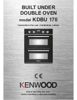
Страница 1: ...BUILT UNDER DOUBLE OVEN model KDBU 170 Instructions for use Installation advice Before operating this oven please read these instructions carefully ...

Страница 2: ...2 ...

Страница 3: ...ol Panel How to use the conventional top oven How to use the multifunction bottom main oven Digital electronic programmer main oven only Cleaning Maintenance Advice for the Installer Installation Electrical installation Guarantee 4 5 6 7 8 9 11 12 16 17 19 20 25 26 27 33 34 35 36 ...

Страница 4: ...or to others in the event that doubts should arise relating to its operation This appliance must be used only for the task it has ex plicitly been designed for that is for cooking foodstuffs Any other form of usage is to be considered as inappropriate and therefore dangerous The manufacturer declines all responsibility in the event of damage caused by improper incorrect or illogical use of the app...

Страница 5: ...ces As a reminder of the need to dispose of household appliances separately the product is marked with a crossed out wheeled dustbin DECLARATION OF CE CONFORMITY This built under double oven has been designed constructed and marketed in compliance with Safety requirements of the Low voltage Directive 2006 95 EC Safety requirements of the EMC Directive 2004 108 EC Requirements of EU Directive 93 68...

Страница 6: ...lity which limits their ability to use the appliance should have a responsible person to instruct them in its use The instructor should be satisfied that they can use the appliance without danger to themselves or their surroundings During and after use of the appliance certain parts will become very hot Do not touch hot parts Care should be taken to avoid touching heating elements inside the ovens...

Страница 7: ... s Always stand back from the oven s when opening the oven door s to allow steam and hot air to escape before removing the food Safe food handling Leave food in the oven s for as short a time as possible before and after cooking This is to avoid contamination by organisms which may cause food poisoning Take particular care during warmer weather This appliance is for domestic use only Do not operat...

Страница 8: ...Your appliance has been fitted with a cooling fan to achieve optimum efficiency of the controls and to ensure lower surface temperatures are maintained When the top oven is operating the cooling fan motor is always ON When only the bottom main oven is operating the cooling fan motor switches ON OFF depending on temperature Depending on cooking temperatures and times the cooling fan may run on even...

Страница 9: ...15 minutes in the mode in order to eliminate any traces of grease from the electrical elements OPERATING PRINCIPLES Heating and cooking in the conventional oven are obtained a by natural convection The heat is produced by the upper and lower heating elements b by radiation The heat is radiated by the infrared grill element Fig 2 2 Fig 2 1 2 HOW TO USE THE CONVENTIONAL TOP OVEN Attention The oven d...

Страница 10: ...s TRADITIONAL CONVECTION COOKING The upper and lower heating elements are switched on The heat is diffused by natural convection and the temperature must be regulated between 50 C and the maximum position with the thermostat knob It is necessary to preheat the oven before introducing the foods to be cooked Recommended for For foods which require the same cooking temperature both internally and ext...

Страница 11: ...me Attention The oven door becomes very hot during operation Keep children away The external parts of the oven become hot during operation Keep children well out of reach OVEN COOKING Before introducing the food preheat the oven to the desired temperature For a correct preheating operation it is advisable to remove the tray from the oven and introduce it together with the food when the oven has re...

Страница 12: ...al convection The heat is produced by the upper and lower heating elements b by forced convection A fan sucks in the air contained in the oven muffle which sends it through the circular heating element and then sen ds it back through the muffle Before the hot air is sucked back again by the fan to repeat the described cycle it envelops the food in the oven provo king a complete and rapid cooking I...

Страница 13: ... Rotate the knob clockwise to set the oven for one of the following functions OVEN LIGHT By turning the knob onto this setting we light the oven cavity The oven remains alight while any of the functions is on TRADITIONAL CONVECTION COOKING The upper and lower heating elements are switched on The heat is diffused by natural convection and the temperature must be regulated between 50 C and the maxim...

Страница 14: ...IR COOKING The circular element and the fan are on The heat is diffused by forced convection and the temperature must be regulated between 50 C and the maximum position with the thermostat knob It is not necessary to preheat the oven Recommended for For foods that must be well done on the outside and tender or rare on the inside i e lasa gna lamb roast beef whole fish etc VENTILATED GRILL COOKING ...

Страница 15: ...ll out of reach OVEN COOKING Before introducing the food preheat the oven to the desired temperature For a correct preheating operation it is advisable to remove the tray from the oven and introduce it toge ther with the food when the oven has reached the desired temperature Check the cooking time and turn off the oven 5 minutes before the theoretical time to recu perate the stored heat STERILIZAT...

Страница 16: ... oven for about 5 minutes Introduce the food to be cooked positioning the rack as close to the grill as possible The dripping pan should be placed under the rack to catch the cooking juices and fats Grilling with the oven door closed It is recommended that you do not grill for longer than 30 minutes at anyone time Attention The oven door becomes very hot during operation Keep children away The ext...

Страница 17: ...usly for more than 2 seconds setting the clock setting the timer vo lume by touching once along with the MODE key to cancel automatic cooking at any time MODE Function selection tou ched for more than 2 se conds setting the clock only after first connection or after a power fai lure timer automatic cooking dur duration how long the food will take to cook by touching the MODE key again automatic co...

Страница 18: ...tic program after setting the clock the oven starts to operate in the selected function manual co oking The symbol is steady illuminated USING THE TIMER You can use the timer at any time even when the oven is not in use The timer does not turn the oven off The timer can be set for up to 23 hours and 59 minutes To set the timer touch the MODE key for more than 2 seconds the symbol flashes than the ...

Страница 19: ...cooking time Note while dur is displayed you can change to End just by touching one time the MODE key within 8 seconds from the last selection If there is time to wait before cooking starts the current time of day and AUTO will show in the clock display The oven will switch off but is now set for automatic cooking If you are already at home to turn the oven on and only want the oven to turn off au...

Страница 20: ...n juice tomato sauce vinegar etc can damage the ena mel if left too long STAINLESS STEEL ALUMINIUM PARTS AND SILK SCREEN PRINTED SURFACES Clean using an appropriate product Always dry thoroughly IMPORTANT these parts must be cleaned very carefully to avoid scratching and abra sion You are advised to use a soft cloth and neutral soap CAUTION Do not use abrasive substan ces or non neutral detergents...

Страница 21: ...ig 5 1a 5 1b Slide into the guides the shelf and the tray fig 5 2a 5 2b The shelf must be fitted so that the safety catch which stops it sliding out faces the inside of the oven To dismantle operate in reverse order Fig 5 1b Fig 5 2a Fig 5 2b Fig 5 1a TOP OVEN BOTTOM MAIN OVEN ...

Страница 22: ...Let the oven cool down and pay special attention no to touch the hot heating ele ments inside the oven cavity REPLACING THE OVEN LIGHT WARNING Ensure the appliance is switched off before replacing the lamp to avoid the possibility of electric shock Let the oven cavity and the heating elements to cool down Switch off the electrical supply Unscrew the protective cover C figs 5 3a 5 3b Unscrew and re...

Страница 23: ...nges fig 5 4b Hold the door as shown in fig 5 4 Gently close the door fig 5 4c until left and right hinge levers A are ho oked to part B of the door fig 5 4b Withdraw the hinge hooks from their location following arrow C fig 5 4d Rest the door on a soft surface To replace the door repeat the above steps in reverse order B A C Fig 5 4d Fig 5 4 Fig 5 4c Fig 5 4b Fig 5 4a ...

Страница 24: ...emoving the inner pane of glass 1 Lock the door open Fully open the oven door fig 5 5a Fully open the lever A on the left and right hinges Fig 5 5b Gently close the door fig 5 5c until left and right hinge levers A are ho oked to part B of the door fig 5 5b 2 Remove the inner pane Top oven door only Remove the seal G by unhooking the no 3 fixing hooks fig 5 5d Gently pull out the inner pane of gla...

Страница 25: ...it to the retainers H fig 5 6c Top oven door only Reassemble the seal G in the correct way fig 5 6d by hooking the no 3 fixing hooks in the proper holes Unlock the oven door by opening it completely and closing the lever A on the left and right hinges Fig 5 6e The top oven door has a sealed gasket in the top part It is normal the opened gap between the top edge of the inner glass and the sealed ga...

Страница 26: ...r handle s WARNING When correctly installed your product meets all safety requirements laid down for this type of product category However special care should be taken around the rear or the underneath of the ap pliance as these areas are not designed orintended to be touched and may contain sharp or rough edges that may cause injury INSTALLATION SERVICE REGULATIONS UNITED KINGDOM It is a legal re...

Страница 27: ...stallation A between Existing Side Cabinets 560 or 600 mm GAP figs 6 1a 6 1b 6 2a 6 2c Installation B between Side Cabinets by Removing Provious Housing figs 6 2b 6 2c Installation C by Using Housing Unit figs 6 3a 6 3b 6 3c CAUTION Do not lift the double oven by the door handle s WARNING We would point out that the adhesive which bonds the plastic laminate to the fur niture must withstand tempera...

Страница 28: ...VING PRO VIOUS HOUSING figs 6 2b 6 2c Remove previous housing Mount the 2 two metal supports B supplied with the appliance in a separate kit as indicated in Fig 6 2c Prepare 2 wood uprights A width 20 50 mm thickness 18 mm length 650 mm mount the 2 wood uprights A to the cabinet walls as indicated in figure Build in the double oven making it slide on the metal supports B 544 20 538 718 595 42 560 ...

Страница 29: ...INSTALLATION B WARNING VERY IMPORTANT The underside of the cabinet shall be opened to allow correct air circulation 600 mm Gap Fig 6 2a Pre existing 600 mm cabinetry Fig 6 2b Fig 6 2c Measure calculated from the underneath of the worktop to the top support base of the B supports Support base ...

Страница 30: ...b Screw oven base housing to adjoining cabinetry by suitable screws not supplied as indicated in figure 6 3c Check the position of the cabinet legs to ensure the cut out does not interfere with the legs support Otherwise the cabinet may have to be removed as in INSTALLATION TYPE B Mount the 2 two metal supports B supplied with the appliance in a separate kit as indicated in Figs 6 3c Build in the ...

Страница 31: ...595 B Support base Fig 6 3a Fig 6 3b Fig 6 3c Cabinet for installing the oven Remove single oven shelf if fitted Measure calculated from the underneath of the worktop to the top support base of the B supports 15 15 30 25 18 18 36 30 INSTALLATION C ...

Страница 32: ...uate air circulation may greatly impair the performance of your double oven and may affect adjacent cabinets due to an increase in temperature Adjust the hinges of furniture door adjacent to the double oven to allow a 5 7 mm gap between the furniture door and the oven frame IMPORTANT If installing a base panel lea ve a space as indicated in fig 6 5 to allow air circulation 200 10 10 mm 2 mm Fig 6 ...

Страница 33: ...r To ensure the trim is not damaged due to the appliance being placed on the floor the ap pliance should be suitably supported as in below illustrations After installation the appliance door should be slowly opened to ensure no damage has occurred No responsibility for lower trim damage will be accepted if these instructions have not been followed OVEN DOOR LOWER TRIM AIR FLOW Fig 6 7 ...

Страница 34: ...f 3 mm betwe en the appliance and the mains The power supply cable must not touch the hot parts and must be posi tioned so that it does not exceed 75 C at any point Once the appliance has been installed the switch must always be accessible If the power supply cable not supplied with the appliance is damaged it must be substituted by a suitable cable The connection of the appliance to earth is mand...

Страница 35: ...clamp fig 7 2 Insert the mains cable type H05RR F or H05VV F 3 x 2 5 mm2 section into the cable protector P Connect the phase neutral and earth cables to the mains terminal connection block D fig 7 2 EARTH N NEUTRAL L LIVE Attention Make sure the wires have been well inserted into the contacts and have been screwed down well Refit the cable clamp so that it clamps the outer sleeving of the cable a...

Страница 36: ...er undertakes within the specified period to repair or replace free of charge any parts of the appliance found to be defective provided that We are promptly informed of the defect The appliance is installed and used in accordance with the written instructions en closed with the appliance The appliance is used only on an electrical supply as indicated on the rating label fixed to the appliance The ...

Страница 37: ...37 ...

Страница 38: ...38 ...

Страница 39: ...et are given as simply indicative The manufacturer reserves the right considering the characteristics of the models described here at any time and without notice to make eventual necessary modifications for their construction or for commercial needs ...

Страница 40: ...Code 1104093 ß2 ...

Отзывы: