Mechanical installation
Kendrion INTORQ | BA 14.0217 | 07/2021
46
Notice
Do not push the feeler gauge in more than 10 mm between the armature plate and the stator!
5. Check the air gap near the screws using a feeler gauge. These values must match the specifications
for s
LN
found in the table Characteristics for air gap specifications, Page 23.
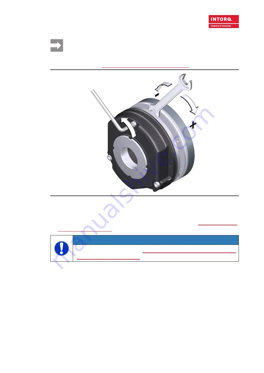
Fig. 19:
Adjusting the air gap
6. If the measured value s
L
is outside of the tolerance s
LN
, readjust this dimension. Loosen the socket
head cap screws slightly and adjust the air gap (turn the sleeve bolts using a wrench).
7. Use a torque wrench to tighten the socket head cap screws (refer to the Figure Tightening the screws
with a torque wrench, Page 45).
NOTICE
Tightening torques: refer to the table Characteristics: screw kit for brake assembly on sep-
arately screwed-on flange, Page 24.


