


11
WORKING CONDITIONS
The hydraulic turning device, or rotator, is designed for use on a hydraulically-powered
lifting crane, e.g. cranes that handle timber or single items. The rotator axle is fitted to lifting
equipment, e.g. a grapple, which grips the load. The load can be rotated horizontally using
the rotator. The hydraulics are connected to the lifting equipment through the rotator axle.
The maximum permissible load on the lifting equipment must not exceed the corresponding
value for the rotator. When the rotator is in use, the hydraulic oil must be at the correct working
temperature and satisfy standard viscosity values.
INSTALLATION INSTRUCTIONS
•
Rotator connection to the crane
•
The rotator must be connected to the end of the crane boom using a link.
•
The rotator must always be suspended freely and vertically in the direction of the axle.
The link pins must be locked in place using clip pins.
•
The rotator is connected to a bushing on the lifting equipment using a pin that is locked
in place with clip pins.
CONNECTING THE ROTATOR TO THE CRANE HYDRAULIC SYSTEM
Turning the rotator
: The system should be thoroughly cleaned. Once the hydraulic system
has reached working temperature, the oil should be circulated to channel any impurities to the
filter. The hoses for the rotator's turning unit are connected together using intermediary nipples
before the rotator. Oil can circulate in this line for at least 5 minutes. The rotator is connected
to the crane's control valve via suitable hoses and pipes. The crane must be equipped with
pressure-limiting valves that limit the pressure going to the rotator to a maximum of 200 bar. If a
higher pressure is possible, pressure-limiting valves should be installed on the rotator's hydraulic
line. The oil flow for rotator rotation is regulated using control nipples. The rotational direction
of the rotator and grapple movement must correspond to the markings on the control levers. If
rotation is too slow, the rotator's movement speed must be checked. Control nipple openings
have been factory-set to a diameter of 1.5 mm. They can be enlarged in 0.1 mm increments.
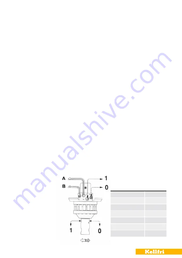
ROTATOR LEAD-THROUGH
When connecting the hydraulics, it should be noted that the maximum pressure in the
pressure duct is 200 bar and that the marked duct in the rotator's upper cover (upper duct)
and the axle must be linked to the opening side of the cylinder on the lifting equipment, e.g.
a grapple. When the grapple opens, it should be noted that the cylinder movement does not
extend fully to keep the duct under pressure as this pressure is an unnecessary load on the
rotator. The crane and equipment must be compliant with the Machinery Directive.
A, B = Reverse flow
1 = Grapple loader closed
0 = Grapple loader open
Technical data
KR07
Turning angle
Unlimited
Max. operating pressure
200 bar
Rec. l/min.
10
Torque (200 bar)
350 Nm
Max. axial force
20 kN
Max. permissible load
1000 kg
Weight
17 kg
Содержание 21-GL36
Страница 19: ...19 Table of Contents 21 GL36 PINS 21 GL36 BUSHINGS...
Страница 25: ...25 Table of Contents 21 GL47 BUSHINGS 21 GL47 PINS...
Страница 34: ...34 Table of Contents NOTES...